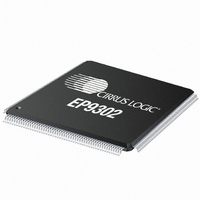
EP9302-CQZ Cirrus Logic Inc, EP9302-CQZ Datasheet - Page 764

EP9302-CQZ
Manufacturer Part Number
EP9302-CQZ
Description
IC ARM9 SOC PROCESSOR 208LQFP
Manufacturer
Cirrus Logic Inc
Series
EP9r
Datasheets
1.EP9307-CRZ.pdf
(824 pages)
2.EP9302-IQZ.pdf
(42 pages)
3.EP9302-IQZ.pdf
(4 pages)
4.EP9302-IQZ.pdf
(40 pages)
Specifications of EP9302-CQZ
Program Memory Type
ROMless
Package / Case
208-LQFP
Core Processor
ARM9
Core Size
16/32-Bit
Speed
200MHz
Connectivity
EBI/EMI, Ethernet, I²C, IrDA, SPI, UART/USART, USB
Peripherals
AC'97, DMA, I²:S, LED, MaverickKey, POR, PWM, WDT
Number Of I /o
19
Ram Size
32K x 8
Voltage - Supply (vcc/vdd)
1.65 V ~ 3.6 V
Data Converters
A/D 5x12b
Oscillator Type
External
Operating Temperature
0°C ~ 70°C
Processor Series
EP93xx
Core
ARM920T
Data Bus Width
32 bit
Data Ram Size
16 bit
Interface Type
USB, USART, SPI
Maximum Clock Frequency
200 MHz
Number Of Programmable I/os
37
Mounting Style
SMD/SMT
3rd Party Development Tools
MDK-ARM, RL-ARM, ULINK2
Development Tools By Supplier
EDB9302A-Z
Controller Family/series
(ARM9)
No. Of I/o's
19
Ram Memory Size
16MB
Cpu Speed
200MHz
No. Of Timers
4
Embedded Interface Type
AC97, I2S, SPI, UART, USB
Rohs Compliant
Yes
Lead Free Status / RoHS Status
Lead free / RoHS Compliant
For Use With
598-1132 - KIT DEVELOPMENT EP9302 ARM9
Eeprom Size
-
Program Memory Size
-
Lead Free Status / Rohs Status
Lead free / RoHS Compliant
Other names
598-1137
Available stocks
Company
Part Number
Manufacturer
Quantity
Price
Company:
Part Number:
EP9302-CQZ
Manufacturer:
Cirrus
Quantity:
3 295
Company:
Part Number:
EP9302-CQZ
Manufacturer:
ALTERA
Quantity:
672
Part Number:
EP9302-CQZ
Manufacturer:
CYPRESS/赛普拉斯
Quantity:
20 000
- EP9307-CRZ PDF datasheet
- EP9302-IQZ PDF datasheet #2
- EP9302-IQZ PDF datasheet #3
- EP9302-IQZ PDF datasheet #4
- Current page: 764 of 824
- Download datasheet (13Mb)
26
26-2
Keypad Interface
EP93xx User’s Guide
26.2 Theory of Operation
The circuitry scans an array of up to 64 keys. The keys are normally open, single pole
contacts arranged in an array of 8 rows by 8 columns. The array may be partially filled. The
key array rows are designated as ROW0 through ROW7, and the columns are designated as
COL0 through COL7.
Any 1 or 2 keys in the array that are pressed are de-bounced and decoded. If more than 2
keys are pressed, only the keys or apparent keys in the array with the lowest address will be
decoded.
Keys or apparent keys with address values greater than that of the lowest two will be ignored.
An apparent key is a condition that may occur when more than 2 keys are pressed. Apparent
keys are caused by alternate current paths in the key array.
A key address is the binary row number concatenated with the binary column address. Key
addresses range from 0x00 to 0x3F. A diagram of the key array is shown in
The circuitry scans the key array by driving each ROW line low, one line at a time. At the end
of each ROW time period, column data is read. The key array column lines are registered and
decoded by a multiplexer. The column address selects the column multiplexer input. Each of
the column lines is passively pulled up by the chip.
When a key is pressed, the column line for the key will be driven low when the row which
contains the key is driven low. On the next key array scan, the output of the multiplexer in the
chip will be asserted active when the row and column is the same as the key address. When
the multiplexer output is active then the key is detected and the address is stored, if it is one
of the first two from the start of a key array scan.
When more than 2 keys are pressed, it is possible to detect apparent keys. Apparent keys
look like actual pressed keys to the device but are not. An example of an apparent key is
described in
“Apparent Key
Detection”.
Copyright 2007 Cirrus Logic
Figure
26-2.
DS785UM1
Related parts for EP9302-CQZ
Image
Part Number
Description
Manufacturer
Datasheet
Request
R

Part Number:
Description:
IC ARM9 SOC PROCESSOR 208LQFP
Manufacturer:
Cirrus Logic Inc
Datasheet:

Part Number:
Description:
High Performance, Entry Level ARM9 SoC
Manufacturer:
Cirrus Logic Inc

Part Number:
Description:
MCU, MPU & DSP Development Tools Eval Bd Hgh-Prfrmnc ARM9 SOC Processor
Manufacturer:
Cirrus Logic Inc
Datasheet:

Part Number:
Description:
Development Kit
Manufacturer:
Cirrus Logic Inc
Datasheet:

Part Number:
Description:
Development Kit
Manufacturer:
Cirrus Logic Inc
Datasheet:

Part Number:
Description:
High-efficiency PFC + Fluorescent Lamp Driver Reference Design
Manufacturer:
Cirrus Logic Inc
Datasheet:

Part Number:
Description:
Development Kit
Manufacturer:
Cirrus Logic Inc
Datasheet:

Part Number:
Description:
Development Kit
Manufacturer:
Cirrus Logic Inc
Datasheet:

Part Number:
Description:
Development Kit
Manufacturer:
Cirrus Logic Inc
Datasheet:

Part Number:
Description:
Development Kit
Manufacturer:
Cirrus Logic Inc
Datasheet:

Part Number:
Description:
Development Kit
Manufacturer:
Cirrus Logic Inc
Datasheet:

Part Number:
Description:
Ref Bd For Speakerbar MSA & DSP Products
Manufacturer:
Cirrus Logic Inc


