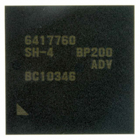
D6417760BP200ADV Renesas Electronics America, D6417760BP200ADV Datasheet - Page 329

D6417760BP200ADV
Manufacturer Part Number
D6417760BP200ADV
Description
IC SUPER H MPU ROMLESS 256BGA
Manufacturer
Renesas Electronics America
Series
SuperH® SH7750r
Datasheet
1.D6417760BP200ADV.pdf
(1418 pages)
Specifications of D6417760BP200ADV
Core Processor
SH-4
Core Size
32-Bit
Speed
200MHz
Connectivity
Audio Codec, CAN, EBI/EMI, FIFO, I²C, MFI, MMC, SCI, Serial Sound, SIM, SPI, USB
Peripherals
DMA, LCD, POR, WDT
Number Of I /o
69
Program Memory Type
ROMless
Ram Size
48K x 8
Voltage - Supply (vcc/vdd)
1.4 V ~ 1.6 V
Data Converters
A/D 4x10b
Oscillator Type
Internal
Operating Temperature
-40°C ~ 85°C
Package / Case
256-BGA
Lead Free Status / RoHS Status
Lead free / RoHS Compliant
Eeprom Size
-
Program Memory Size
-
Available stocks
Company
Part Number
Manufacturer
Quantity
Price
Company:
Part Number:
D6417760BP200ADV
Manufacturer:
Renesas Electronics America
Quantity:
10 000
- Current page: 329 of 1418
- Download datasheet (9Mb)
9.5.2
When handling multiple interrupts, the interrupt handling routine should include the following
procedures:
1. Branch to the interrupt handling routine of each interrupt source using the INTEVT value as an
2. Clear the interrupt source in the corresponding interrupt handling routine.
3. Save SPC and SSR in the stack.
4. Clear the BL bit in SR, and set the accepted interrupt level in the interrupt mask level bits
5. Write the actual processing.
6. Set the BL bit in SR to 1.
7. Restore SSR and SPC from memory.
8. Execute the RTE instruction.
When these procedures are followed in order, an interrupt of higher priority than the one being
handled can be accepted immediately after step 4. This enables the interrupt response time to be
shortened for urgent processing.
9.5.3
By setting the MAI bit to 1 in ICR, interrupts can be masked while the NMI pin is low,
irrespective of the BL and IMASK bits in SR.
• In normal operation and sleep mode
• In standby mode
offset to identify the interrupt source.
(IMASK3 to IMASK0) in SR.
All interrupts are masked while the NMI pin is low. However, an NMI interrupt only is
generated by a transition at the NMI pin.
All interrupts are masked while the NMI pin is low, and an NMI interrupt is not generated by a
transition at the NMI pin. Therefore, standby mode cannot be cleared by an NMI interrupt
while the MAI bit is set to 1.
Multiple Interrupts
Interrupt Masking with MAI Bit
Rev. 2.00 Feb. 12, 2010 Page 245 of 1330
REJ09B0554-0200
Related parts for D6417760BP200ADV
Image
Part Number
Description
Manufacturer
Datasheet
Request
R

Part Number:
Description:
KIT STARTER FOR M16C/29
Manufacturer:
Renesas Electronics America
Datasheet:

Part Number:
Description:
KIT STARTER FOR R8C/2D
Manufacturer:
Renesas Electronics America
Datasheet:

Part Number:
Description:
R0K33062P STARTER KIT
Manufacturer:
Renesas Electronics America
Datasheet:

Part Number:
Description:
KIT STARTER FOR R8C/23 E8A
Manufacturer:
Renesas Electronics America
Datasheet:

Part Number:
Description:
KIT STARTER FOR R8C/25
Manufacturer:
Renesas Electronics America
Datasheet:

Part Number:
Description:
KIT STARTER H8S2456 SHARPE DSPLY
Manufacturer:
Renesas Electronics America
Datasheet:

Part Number:
Description:
KIT STARTER FOR R8C38C
Manufacturer:
Renesas Electronics America
Datasheet:

Part Number:
Description:
KIT STARTER FOR R8C35C
Manufacturer:
Renesas Electronics America
Datasheet:

Part Number:
Description:
KIT STARTER FOR R8CL3AC+LCD APPS
Manufacturer:
Renesas Electronics America
Datasheet:

Part Number:
Description:
KIT STARTER FOR RX610
Manufacturer:
Renesas Electronics America
Datasheet:

Part Number:
Description:
KIT STARTER FOR R32C/118
Manufacturer:
Renesas Electronics America
Datasheet:

Part Number:
Description:
KIT DEV RSK-R8C/26-29
Manufacturer:
Renesas Electronics America
Datasheet:

Part Number:
Description:
KIT STARTER FOR SH7124
Manufacturer:
Renesas Electronics America
Datasheet:

Part Number:
Description:
KIT STARTER FOR H8SX/1622
Manufacturer:
Renesas Electronics America
Datasheet:

Part Number:
Description:
KIT DEV FOR SH7203
Manufacturer:
Renesas Electronics America
Datasheet:


