HD6413003TF16V Renesas Electronics America, HD6413003TF16V Datasheet - Page 507
HD6413003TF16V
Manufacturer Part Number
HD6413003TF16V
Description
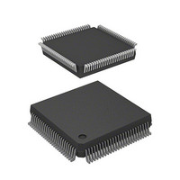
MCU 5V 0K PB-FREE 112-QFP
Manufacturer
Renesas Electronics America
Series
H8® H8/300Hr
Datasheet
1.D13003TF16V.pdf
(717 pages)
Specifications of HD6413003TF16V
Core Size
16-Bit
Oscillator Type
Internal
Core Processor
H8/300H
Speed
16MHz
Connectivity
SCI
Peripherals
DMA, PWM, WDT
Number Of I /o
50
Program Memory Type
ROMless
Ram Size
512 x 8
Voltage - Supply (vcc/vdd)
2.7 V ~ 5.5 V
Data Converters
A/D 8x10b
Operating Temperature
-20°C ~ 75°C
Package / Case
112-QFP
No. Of I/o's
58
Ram Memory Size
512Byte
Cpu Speed
16MHz
No. Of Timers
11
No. Of Pwm Channels
4
Digital Ic Case Style
QFP
Supply Voltage
RoHS Compliant
Controller Family/series
H8/300H
Rohs Compliant
Yes
Lead Free Status / RoHS Status
Lead free / RoHS Compliant
Eeprom Size
-
Program Memory Size
-
Lead Free Status / RoHS Status
Lead free / RoHS Compliant
Available stocks
Company
Part Number
Manufacturer
Quantity
Price
Company:

Part Number:
HD6413003TF16V
Manufacturer:
ITT
Quantity:
12 000
Company:
Part Number:
HD6413003TF16V
Manufacturer:
RENESAS
Quantity:
36
Part Number:
HD6413003TF16V
Manufacturer:
RENESAS/瑞萨
Quantity:
20 000


14.2 Register Descriptions
14.2.1 A/D Data Registers A to D (ADDRA to ADDRD)
The four A/D data registers (ADDRA to ADDRD) are 16-bit read-only registers that store the
results of A/D conversion.
An A/D conversion produces 10-bit data, which is transferred for storage into the A/D data
register corresponding to the selected channel. The upper 8 bits of the result are stored in the
upper byte of the A/D data register. The lower 2 bits are stored in the lower byte. Bits 5 to 0 of an
A/D data register are reserved bits that always read 0. Table 14-3 indicates the pairings of analog
input channels and A/D data registers.
The CPU can always read and write the A/D data registers. The upper byte can be read directly,
but the lower byte is read through a temporary register (TEMP). For details see section 14.3, CPU
Interface.
The A/D data registers are initialized to H'0000 by a reset and in standby mode.
Table 14-3 Analog Input Channels and A/D Data Registers
Group 0
AN
AN
AN
AN
Bit
ADDRn
Initial value
Read/Write
(n = A to D)
Analog Input Channel
0
1
2
3
AD9
Group 1
AN
AN
AN
AN
15
R
0
4
5
6
7
AD8
14
R
0
AD7
13
R
0
A/D conversion data
10-bit data giving an
A/D conversion result
AD6
12
R
0
A/D Data Register
ADDRA
ADDRB
ADDRC
ADDRD
AD5
11
R
0
AD4
10
R
0
AD3
487
R
9
0
AD2
R
8
0
AD1
R
7
0
AD0
R
6
0
—
R
5
0
—
R
4
0
Reserved bits
—
R
3
0
—
R
2
0
—
R
1
0
—
R
0
0
Related parts for HD6413003TF16V
Image
Part Number
Description
Manufacturer
Datasheet
Request
R

Part Number:
Description:
KIT STARTER FOR M16C/29
Manufacturer:
Renesas Electronics America
Datasheet:

Part Number:
Description:
KIT STARTER FOR R8C/2D
Manufacturer:
Renesas Electronics America
Datasheet:

Part Number:
Description:
R0K33062P STARTER KIT
Manufacturer:
Renesas Electronics America
Datasheet:

Part Number:
Description:
KIT STARTER FOR R8C/23 E8A
Manufacturer:
Renesas Electronics America
Datasheet:

Part Number:
Description:
KIT STARTER FOR R8C/25
Manufacturer:
Renesas Electronics America
Datasheet:

Part Number:
Description:
KIT STARTER H8S2456 SHARPE DSPLY
Manufacturer:
Renesas Electronics America
Datasheet:

Part Number:
Description:
KIT STARTER FOR R8C38C
Manufacturer:
Renesas Electronics America
Datasheet:

Part Number:
Description:
KIT STARTER FOR R8C35C
Manufacturer:
Renesas Electronics America
Datasheet:

Part Number:
Description:
KIT STARTER FOR R8CL3AC+LCD APPS
Manufacturer:
Renesas Electronics America
Datasheet:
Part Number:
Description:
KIT STARTER FOR RX610
Manufacturer:
Renesas Electronics America
Datasheet:

Part Number:
Description:
KIT STARTER FOR R32C/118
Manufacturer:
Renesas Electronics America
Datasheet:

Part Number:
Description:
KIT DEV RSK-R8C/26-29
Manufacturer:
Renesas Electronics America
Datasheet:

Part Number:
Description:
KIT STARTER FOR SH7124
Manufacturer:
Renesas Electronics America
Datasheet:

Part Number:
Description:
KIT STARTER FOR H8SX/1622
Manufacturer:
Renesas Electronics America
Datasheet:

Part Number:
Description:
KIT DEV FOR SH7203
Manufacturer:
Renesas Electronics America
Datasheet: