HD6413003TF16V Renesas Electronics America, HD6413003TF16V Datasheet - Page 9
HD6413003TF16V
Manufacturer Part Number
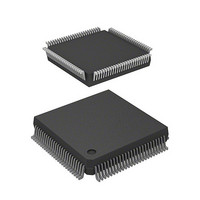
HD6413003TF16V
Description
MCU 5V 0K PB-FREE 112-QFP
Manufacturer
Renesas Electronics America
Series
H8® H8/300Hr
Datasheet
1.D13003TF16V.pdf
(717 pages)
Specifications of HD6413003TF16V
Core Size
16-Bit
Oscillator Type
Internal
Core Processor
H8/300H
Speed
16MHz
Connectivity
SCI
Peripherals
DMA, PWM, WDT
Number Of I /o
50
Program Memory Type
ROMless
Ram Size
512 x 8
Voltage - Supply (vcc/vdd)
2.7 V ~ 5.5 V
Data Converters
A/D 8x10b
Operating Temperature
-20°C ~ 75°C
Package / Case
112-QFP
No. Of I/o's
58
Ram Memory Size
512Byte
Cpu Speed
16MHz
No. Of Timers
11
No. Of Pwm Channels
4
Digital Ic Case Style
QFP
Supply Voltage
RoHS Compliant
Controller Family/series
H8/300H
Rohs Compliant
Yes
Lead Free Status / RoHS Status
Lead free / RoHS Compliant
Eeprom Size
-
Program Memory Size
-
Lead Free Status / RoHS Status
Lead free / RoHS Compliant
Available stocks
Company
Part Number
Manufacturer
Quantity
Price
Company:

Part Number:
HD6413003TF16V
Manufacturer:
ITT
Quantity:
12 000
Company:
Part Number:
HD6413003TF16V
Manufacturer:
RENESAS
Quantity:
36
Part Number:
HD6413003TF16V
Manufacturer:
RENESAS/瑞萨
Quantity:
20 000


5.2
5.3
5.4
5.5
Section 6
6.1
6.2
6.3
6.4
Register Descriptions...................................................................................................... 76
5.2.1
5.2.2
5.2.3
5.2.4
5.2.5
Interrupt Sources............................................................................................................. 87
5.3.1
5.3.2
5.3.3
Interrupt Operation ......................................................................................................... 91
5.4.1
5.4.2
5.4.3
Usage Notes .................................................................................................................... 98
5.5.1
5.5.2
5.5.3
Overview ........................................................................................................................ 101
6.1.1
6.1.2
6.1.3
6.1.4
Register Descriptions...................................................................................................... 104
6.2.1
6.2.2
6.2.3
6.2.4
6.2.5
Operation ........................................................................................................................ 109
6.3.1
6.3.2
6.3.3
6.3.4
6.3.5
6.3.6
6.3.7
Usage Notes .................................................................................................................... 132
6.4.1
System Control Register (SYSCR)................................................................. 76
Interrupt Priority Registers A and B (IPRA, IPRB) ....................................... 77
IRQ Status Register (ISR) .............................................................................. 84
IRQ Enable Register (IER) ............................................................................. 85
IRQ Sense Control Register (ISCR) ............................................................... 86
External Interrupts .......................................................................................... 87
Internal Interrupts ........................................................................................... 88
Interrupt Vector Table ..................................................................................... 88
Interrupt Handling Process ............................................................................. 91
Interrupt Sequence .......................................................................................... 96
Interrupt Response Time................................................................................. 97
Contention between Interrupt and Interrupt-Disabling Instruction ................ 98
Instructions that Inhibit Interrupts .................................................................. 99
Interrupts during EEPMOV Instruction Execution......................................... 99
Bus Controller
Features........................................................................................................... 101
Block Diagram................................................................................................ 102
Input/Output Pins............................................................................................ 103
Register Configuration.................................................................................... 103
Bus Width Control Register (ABWCR) ......................................................... 104
Access State Control Register (ASTCR) ........................................................ 105
Wait Control Register (WCR)......................................................................... 106
Wait State Control Enable Register (WCER) ................................................. 107
Bus Release Control Register (BRCR)........................................................... 108
Area Division.................................................................................................. 109
Chip Select Signals ......................................................................................... 111
Data Bus.......................................................................................................... 112
Bus Control Signal Timing ............................................................................. 113
Wait Modes ..................................................................................................... 121
Interconnections with Memory (Example)..................................................... 127
Bus Arbiter Operation..................................................................................... 129
Connection to Dynamic RAM and Pseudo-Static RAM ................................ 132
............................................................................................ 101
Related parts for HD6413003TF16V
Image
Part Number
Description
Manufacturer
Datasheet
Request
R

Part Number:
Description:
KIT STARTER FOR M16C/29
Manufacturer:
Renesas Electronics America
Datasheet:

Part Number:
Description:
KIT STARTER FOR R8C/2D
Manufacturer:
Renesas Electronics America
Datasheet:

Part Number:
Description:
R0K33062P STARTER KIT
Manufacturer:
Renesas Electronics America
Datasheet:

Part Number:
Description:
KIT STARTER FOR R8C/23 E8A
Manufacturer:
Renesas Electronics America
Datasheet:

Part Number:
Description:
KIT STARTER FOR R8C/25
Manufacturer:
Renesas Electronics America
Datasheet:

Part Number:
Description:
KIT STARTER H8S2456 SHARPE DSPLY
Manufacturer:
Renesas Electronics America
Datasheet:

Part Number:
Description:
KIT STARTER FOR R8C38C
Manufacturer:
Renesas Electronics America
Datasheet:

Part Number:
Description:
KIT STARTER FOR R8C35C
Manufacturer:
Renesas Electronics America
Datasheet:

Part Number:
Description:
KIT STARTER FOR R8CL3AC+LCD APPS
Manufacturer:
Renesas Electronics America
Datasheet:
Part Number:
Description:
KIT STARTER FOR RX610
Manufacturer:
Renesas Electronics America
Datasheet:

Part Number:
Description:
KIT STARTER FOR R32C/118
Manufacturer:
Renesas Electronics America
Datasheet:

Part Number:
Description:
KIT DEV RSK-R8C/26-29
Manufacturer:
Renesas Electronics America
Datasheet:

Part Number:
Description:
KIT STARTER FOR SH7124
Manufacturer:
Renesas Electronics America
Datasheet:

Part Number:
Description:
KIT STARTER FOR H8SX/1622
Manufacturer:
Renesas Electronics America
Datasheet:

Part Number:
Description:
KIT DEV FOR SH7203
Manufacturer:
Renesas Electronics America
Datasheet: