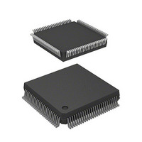
HD6413003TF16V Renesas Electronics America, HD6413003TF16V Datasheet - Page 81

HD6413003TF16V
Manufacturer Part Number
HD6413003TF16V
Description
MCU 5V 0K PB-FREE 112-QFP
Manufacturer
Renesas Electronics America
Series
H8® H8/300Hr
Datasheet
1.D13003TF16V.pdf
(717 pages)
Specifications of HD6413003TF16V
Core Size
16-Bit
Oscillator Type
Internal
Core Processor
H8/300H
Speed
16MHz
Connectivity
SCI
Peripherals
DMA, PWM, WDT
Number Of I /o
50
Program Memory Type
ROMless
Ram Size
512 x 8
Voltage - Supply (vcc/vdd)
2.7 V ~ 5.5 V
Data Converters
A/D 8x10b
Operating Temperature
-20°C ~ 75°C
Package / Case
112-QFP
No. Of I/o's
58
Ram Memory Size
512Byte
Cpu Speed
16MHz
No. Of Timers
11
No. Of Pwm Channels
4
Digital Ic Case Style
QFP
Supply Voltage
RoHS Compliant
Controller Family/series
H8/300H
Rohs Compliant
Yes
Lead Free Status / RoHS Status
Lead free / RoHS Compliant
Eeprom Size
-
Program Memory Size
-
Lead Free Status / RoHS Status
Lead free / RoHS Compliant
Available stocks
Company
Part Number
Manufacturer
Quantity
Price
Company:
Part Number:
HD6413003TF16V
Manufacturer:
ITT
Quantity:
12 000
Company:
Part Number:
HD6413003TF16V
Manufacturer:
RENESAS
Quantity:
36
Part Number:
HD6413003TF16V
Manufacturer:
RENESAS/瑞萨
Quantity:
20 000
- Current page: 81 of 717
- Download datasheet (2Mb)
Bits 6 to 4—Standby Timer Select (STS2 to STS0): These bits select the length of time the CPU
and on-chip supporting modules wait for the internal clock oscillator to settle when software
standby mode is exited by an external interrupt. Set these bits so that the waiting time will be at
least 8 ms at the system clock rate. For further information about waiting time selection, see
section 17.4.3, Selection of Oscillator Waiting Time after Exit from Software Standby Mode.
Bit 6
STS2
0
0
0
0
1
1
Bit 3—User Bit Enable (UE): Selects whether to use the UI bit in the condition code register as a
user bit or an interrupt mask bit.
Bit 3
UE
0
1
Bit 2—NMI Edge Select (NMIEG): Selects the valid edge of the NMI input.
Bit 2
NMIEG
0
1
Bit 1—Reserved: Read-only bit, always read as 1.
Bit 0—RAM Enable (RAME): Enables or disables the on-chip RAM. The RAME bit is
initialized by the rising edge of the RES signal. It is not initialized in software standby mode.
Bit 0
RAME
0
1
Bit 5
STS1
0
0
1
1
0
1
Description
UI bit in CCR is used as an interrupt mask bit
UI bit in CCR is used as a user bit
Description
An interrupt is requested at the falling edge of NMI
An interrupt is requested at the rising edge of NMI
Description
On-chip RAM is disabled
On-chip RAM is enabled
Bit 4
STS0
0
1
0
1
—
—
Description
Waiting time = 8192 states
Waiting time = 16384 states
Waiting time = 32768 states
Waiting time = 65536 states
Waiting time = 131072 states
Waiting time = 4 states
61
(Initial value)
(Initial value)
(Initial value)
(Initial value)
Related parts for HD6413003TF16V
Image
Part Number
Description
Manufacturer
Datasheet
Request
R

Part Number:
Description:
KIT STARTER FOR M16C/29
Manufacturer:
Renesas Electronics America
Datasheet:

Part Number:
Description:
KIT STARTER FOR R8C/2D
Manufacturer:
Renesas Electronics America
Datasheet:

Part Number:
Description:
R0K33062P STARTER KIT
Manufacturer:
Renesas Electronics America
Datasheet:

Part Number:
Description:
KIT STARTER FOR R8C/23 E8A
Manufacturer:
Renesas Electronics America
Datasheet:

Part Number:
Description:
KIT STARTER FOR R8C/25
Manufacturer:
Renesas Electronics America
Datasheet:

Part Number:
Description:
KIT STARTER H8S2456 SHARPE DSPLY
Manufacturer:
Renesas Electronics America
Datasheet:

Part Number:
Description:
KIT STARTER FOR R8C38C
Manufacturer:
Renesas Electronics America
Datasheet:

Part Number:
Description:
KIT STARTER FOR R8C35C
Manufacturer:
Renesas Electronics America
Datasheet:

Part Number:
Description:
KIT STARTER FOR R8CL3AC+LCD APPS
Manufacturer:
Renesas Electronics America
Datasheet:

Part Number:
Description:
KIT STARTER FOR RX610
Manufacturer:
Renesas Electronics America
Datasheet:

Part Number:
Description:
KIT STARTER FOR R32C/118
Manufacturer:
Renesas Electronics America
Datasheet:

Part Number:
Description:
KIT DEV RSK-R8C/26-29
Manufacturer:
Renesas Electronics America
Datasheet:

Part Number:
Description:
KIT STARTER FOR SH7124
Manufacturer:
Renesas Electronics America
Datasheet:

Part Number:
Description:
KIT STARTER FOR H8SX/1622
Manufacturer:
Renesas Electronics America
Datasheet:

Part Number:
Description:
KIT DEV FOR SH7203
Manufacturer:
Renesas Electronics America
Datasheet:


