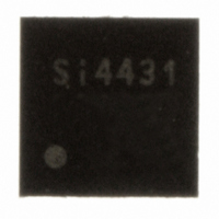
SI4431-A0-FM Silicon Laboratories Inc, SI4431-A0-FM Datasheet - Page 36

SI4431-A0-FM
Manufacturer Part Number
SI4431-A0-FM
Description
IC TXRX ISM 930MHZ 3.6V 20-QFN
Manufacturer
Silicon Laboratories Inc
Specifications of SI4431-A0-FM
Package / Case
20-QFN
Mfg Application Notes
Transitioning SI4430/31 to Rev B
Frequency
240MHz ~ 930MHz
Data Rate - Maximum
128kbps
Modulation Or Protocol
FSK, GFSK, OOK
Power - Output
13dBm
Sensitivity
-118dBm
Voltage - Supply
1.8 V ~ 3.6 V
Current - Receiving
18.5mA
Current - Transmitting
28mA
Data Interface
PCB, Surface Mount
Antenna Connector
PCB, Surface Mount
Operating Temperature
-40°C ~ 85°C
Number Of Receivers
2
Number Of Transmitters
1
Wireless Frequency
240 MHz to 930 MHz
Output Power
13 dBm
Operating Supply Voltage
1.8 V to 3.6 V
Maximum Operating Temperature
+ 85 C
Mounting Style
SMD/SMT
Maximum Supply Current
28 mA
Minimum Operating Temperature
- 40 C
Modulation
FSK, GFSK, OOK
Lead Free Status / RoHS Status
Lead free / RoHS Compliant
Applications
-
Memory Size
-
Lead Free Status / RoHS Status
Lead free / RoHS Compliant, Lead free / RoHS Compliant
Other names
336-1633-5
Available stocks
Company
Part Number
Manufacturer
Quantity
Price
Company:
Part Number:
SI4431-A0-FMR
Manufacturer:
SILICON
Quantity:
3 500
Part Number:
SI4431-A0-FMR
Manufacturer:
SILICONLABS/èٹ¯ç§‘
Quantity:
20 000
Si4431
4.5. PN9 Mode
In this mode the TX Data is generated internally using a pseudorandom (PN9 sequence) bit generator. The primary
purpose of this mode is for use as a test mode to observe the modulated spectrum without having to load/provide
data.
4.6. Synchronous vs. Asynchronous
In Asynchronous mode no clock is used to synchronize the data to the internal modulator. This mode can only be
used with FSK. The advantage of this mode that it saves a microcontroller pin because no data clock is required.
The disadvantage is that you don’t get the clean spectrum and limited BW of GFSK. If Asynchronous FSK is used
the TX_DR register should be set to its maximum value.
36
Matching
Matching
Figure 13. Direct Asynchronous Mode Example
Figure 12. Direct Synchronous Mode Example
MOD(Data)
MOD(Data)
VDD_RF
RXp
RXn
VR_IF
RXp
RXn
VR_IF
VDD_RF
TX
TX
DataCLK
VDD_DIG
VDD_DIG
SCLK
SCLK
SDO
SDO
SDI
SDI
NC
NC
Preliminary Rev. 0.4
nIRQ
nSEL
SCK
MOSI
MISO
MOD
DATACLK
nIRQ
nSEL
SCK
MOSI
MISO
MOD
nRES
nRES
C
C
Direct synchronous modulation. Full
control over the standard SPI & using
interrupt. Bitrate clock and modulation
via GPIO’s.
GPIO configuration
GP0 : power-on-reset (default)
GP1 : TX DATA clock output
GP2 : TX DATA input
Direct asynchronous FSK modulation.
Modulation data via GPIO2, no data
clock needed in this mode.
GPIO configuration
GP0 : power-on-reset (default)
GP1: not utilized
GP2 : TX DATA input


