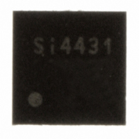
SI4431-A0-FM Silicon Laboratories Inc, SI4431-A0-FM Datasheet - Page 78

SI4431-A0-FM
Manufacturer Part Number
SI4431-A0-FM
Description
IC TXRX ISM 930MHZ 3.6V 20-QFN
Manufacturer
Silicon Laboratories Inc
Specifications of SI4431-A0-FM
Package / Case
20-QFN
Mfg Application Notes
Transitioning SI4430/31 to Rev B
Frequency
240MHz ~ 930MHz
Data Rate - Maximum
128kbps
Modulation Or Protocol
FSK, GFSK, OOK
Power - Output
13dBm
Sensitivity
-118dBm
Voltage - Supply
1.8 V ~ 3.6 V
Current - Receiving
18.5mA
Current - Transmitting
28mA
Data Interface
PCB, Surface Mount
Antenna Connector
PCB, Surface Mount
Operating Temperature
-40°C ~ 85°C
Number Of Receivers
2
Number Of Transmitters
1
Wireless Frequency
240 MHz to 930 MHz
Output Power
13 dBm
Operating Supply Voltage
1.8 V to 3.6 V
Maximum Operating Temperature
+ 85 C
Mounting Style
SMD/SMT
Maximum Supply Current
28 mA
Minimum Operating Temperature
- 40 C
Modulation
FSK, GFSK, OOK
Lead Free Status / RoHS Status
Lead free / RoHS Compliant
Applications
-
Memory Size
-
Lead Free Status / RoHS Status
Lead free / RoHS Compliant, Lead free / RoHS Compliant
Other names
336-1633-5
Available stocks
Company
Part Number
Manufacturer
Quantity
Price
Company:
Part Number:
SI4431-A0-FMR
Manufacturer:
SILICON
Quantity:
3 500
Part Number:
SI4431-A0-FMR
Manufacturer:
SILICONLABS/èٹ¯ç§‘
Quantity:
20 000
Si4431
11. Application Notes
11.1. Crystal Selection
The recommended crystal parameters are given in Table 26.
The internal XTAL oscillator will work over a range for the parameters of ESR, CL, C0, and ppm accuracy. Extreme
values may affect the XTAL start-up and sensitivity of the link. For questions regarding the use of a crystal
parameters greatly deviating from the recommend values listed above, please contact customer support.
The crystal used for engineering evaluation and the reference design is the SIWARD –SX2520– 30.0 MHz –
12.0R. Ordering number XTL581200JIG.
11.2. Layout Practice
The following are some general best practice guidelines for PCB layout using the EZRadioPro devices:
78
Bypass capacitors should be placed as close as possible to the pin.
TX/RX matching/layout should mimic reference as much as possible. Failing to do so may cause loss
inperformance.
A solid ground plane is required on the backside of the board under TX/RX matching components
Crystal should be placed as close as possible to the XIN/XOUT pins and should not have VDD traces running
underneath or near it.
The paddle on the backside of the QFN package needs solid grounding and good soldered connection
Use GND stitch vias liberally throughout the board, especially underneath the paddle.
Frequency
30 MHz
60 Ω
ESR
Table 26. Recommended Crystal Parameters
12 pF
Preliminary Rev. 0.4
C
L
5 pF
C
0
Frequency Accuracy
±20 ppm


