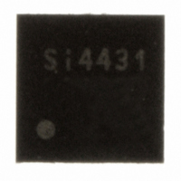
SI4431-A0-FM Silicon Laboratories Inc, SI4431-A0-FM Datasheet - Page 67

SI4431-A0-FM
Manufacturer Part Number
SI4431-A0-FM
Description
IC TXRX ISM 930MHZ 3.6V 20-QFN
Manufacturer
Silicon Laboratories Inc
Specifications of SI4431-A0-FM
Package / Case
20-QFN
Mfg Application Notes
Transitioning SI4430/31 to Rev B
Frequency
240MHz ~ 930MHz
Data Rate - Maximum
128kbps
Modulation Or Protocol
FSK, GFSK, OOK
Power - Output
13dBm
Sensitivity
-118dBm
Voltage - Supply
1.8 V ~ 3.6 V
Current - Receiving
18.5mA
Current - Transmitting
28mA
Data Interface
PCB, Surface Mount
Antenna Connector
PCB, Surface Mount
Operating Temperature
-40°C ~ 85°C
Number Of Receivers
2
Number Of Transmitters
1
Wireless Frequency
240 MHz to 930 MHz
Output Power
13 dBm
Operating Supply Voltage
1.8 V to 3.6 V
Maximum Operating Temperature
+ 85 C
Mounting Style
SMD/SMT
Maximum Supply Current
28 mA
Minimum Operating Temperature
- 40 C
Modulation
FSK, GFSK, OOK
Lead Free Status / RoHS Status
Lead free / RoHS Compliant
Applications
-
Memory Size
-
Lead Free Status / RoHS Status
Lead free / RoHS Compliant, Lead free / RoHS Compliant
Other names
336-1633-5
Available stocks
Company
Part Number
Manufacturer
Quantity
Price
Company:
Part Number:
SI4431-A0-FMR
Manufacturer:
SILICON
Quantity:
3 500
Part Number:
SI4431-A0-FMR
Manufacturer:
SILICONLABS/èٹ¯ç§‘
Quantity:
20 000
8.9. Antenna-Diversity
To mitigate the problem of frequency-selective fading due to multi-path propagation, some transceiver systems use
a scheme known as Antenna Diversity. In this scheme, two antennas are used. Each time the transceiver enters
RX mode the receive signal strength from each antenna is evaluated. This evaluation process takes place during
the preamble portion of the packet. The antenna with the strongest received signal is then used for the remainder
of that RX packet. The same antenna will also be used for the next corresponding TX packet.
This chip fully supports Antenna Diversity with an integrated Antenna Diversity Control Algorithm. By setting
GPIOx[4:0] = 10111 and 11000, the required signal needed to control an external SPDT RF switch (such as PIN
diode or GaAs switch) is made available on the GPIOx pins. The operation of these switches is programmable to
allow for different Antenna Diversity architectures and configurations. The antdiv[2:0] register is found in register
08h. The GPIO pin is capable of sourcing up to 5 mA of current, so it may be used directly to forward-bias a PIN
diode if desired.
When the arrival of the packet is unknown by the receiver the antenna diversity algorithm (antdiv[2:0] = 100 or 101)
will detect both packet arrival and selects the antenna with the strongest signal. The recommended preamble
length to obtain good antenna selection is 8 bytes. A special antenna diversity algorithm (antdiv[2:0] = 110 or 111)
is included that allows for shorter preamble for TDMA like systems where the arrival of the packet is synchronized
to the receiver enable. The recommended preamble length to obtain good antenna selection for synchronized
mode is 4 bytes.
Add R/W Function/Description
08
antdiv[2:0]
R/W
000
001
010
011
100
101
110
111
Operating & Function
Antenna Diversity Algorithm
Antenna Diversity Algorithm
Antenna Diversity Algorithm in Beacon Mode
Antenna Diversity Algorithm in Beacon Mode
Control 2
GPIO Ant1
0
1
0
1
RX/TX State
Table 24. Antenna Diversity Control
antdiv[2] antdiv[1] antdiv[0] rxmpk
D7
Preliminary Rev. 0.4
D6
GPIO Ant2
1
0
1
0
D5
D4
GPIO Ant1
autotx
D3
0
0
1
1
0
1
0
1
enldm ffclrrx
Non RX/TX State
D2
D1
GPIO Ant2
ffclrtx
D0
Si4431
0
0
1
1
0
1
0
1
POR Def.
00h
67


