IPR-HPMCII Altera, IPR-HPMCII Datasheet - Page 37
IPR-HPMCII
Manufacturer Part Number
IPR-HPMCII
Description
IP CORE Renewal Of IP-HPMCII
Manufacturer
Altera
Datasheet
1.IP-HPMCII.pdf
(176 pages)
Specifications of IPR-HPMCII
Software Application
IP CORE, Memory Controllers, SDRAM
Supported Families
Arria II GX, HardCopy III, Stratix III, Stratix IV
Core Architecture
FPGA
Core Sub-architecture
Arria, HardCopy, Stratix
Rohs Compliant
NA
Lead Free Status / RoHS Status
na


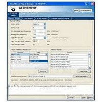
Chapter 3: Parameter Settings
ALTMEMPHY Parameter Settings
Table 3–5. DDR3 SDRAM Timing Parameter Settings (Part 2 of 3)
December 2010 Altera Corporation
t
t
t
t
t
t
t
t
t
t
t
t
t
WTR
AC
DQSCK
DQSQ
DQSS
DH
DS
DSH
DSS
IH
IS
QHS
QH
Parameter Name
1–6
0–750
50–750
50–500
0–0.3
10–600
10–600
0.1–0.5
0.1–0.5
50–1000
65–1000
0–700
0.1–0.6
Range
t
ps
ps
ps
t
ps
ps
t
t
ps
ps
ps
t
CK
CK
CK
CK
CK
Units
Section II. DDR3 SDRAM Controller with ALTMEMPHY IP User Guide
Minimum write-to-read command delay. The controller
waits for this period of time after the end of a write
command before issuing a subsequent read command
to the same bank. This timing parameter is specified in
clock cycles and the value is rounded off to the next
integer.
DQ output access time.
DQS output access time from CK/CK# signals.
The maximum DQS to DQ skew; DQS to last DQ valid,
per group, per access.
Positive DQS latching edge to associated clock edge.
DQ and DM input hold time relative to DQS, which has a
derated value depending on the slew rate of the
differential DQS and DQ/DM signals. Ensure that you
are using the correct number and that the value entered
is referenced to V
max. Refer to
Timing” on page 3–10
to derate this specification.
DQ and DM input setup time relative to DQS, which has
a derated value depending on the slew rate of the
differential DQS signals and DQ/DM signals. Ensure
that you are using the correct number and that the
value entered is referenced to V
or V
Hold Timing” on page 3–10
how to derate this specification.
DQS falling edge hold time from CK.
DQS falling edge to CK setup.
Address and control input hold time, which has a
derated value depending on the slew rate of the CK and
CK# clocks and the address and command signals.
Ensure that you are using the correct number and that
the value entered is referenced to
min or V
and Hold Timing” on page 3–10
about how to derate this specification.
Address and control input setup time, which has a
derated value depending on the slew rate of the CK and
CK# clocks and the address and command signals.
Ensure that you are using the correct number and that
the value entered is referenced to V
min or V
and Hold Timing” on page 3–10
about how to derate this specification.
The maximum data hold skew factor.
DQ output hold time.
(Note 1)
IL
(ac) max. Refer to
IL
IL
(dc) max. Refer to
(ac) max. Refer to
“Derating Memory Setup and Hold
External Memory Interface Handbook Volume 3
REF
(dc), not V
Description
for more information about how
“Derating Memory Setup and
for more information about
“Derating Memory Setup
“Derating Memory Setup
REF
IH
for more information
for more information
(dc) min or V
VREF
(dc), not V
REF
(dc), not V
(dc), not V
IH
IL
(ac) min
(dc)
IH
IH
(dc)
(ac)
3–9
Related parts for IPR-HPMCII
Image
Part Number
Description
Manufacturer
Datasheet
Request
R

Part Number:
Description:
IP NIOS II MEGACORE RENEW
Manufacturer:
Altera
Datasheet:
Part Number:
Description:
IP CORE Renewal Of IP-XAUIPCS
Manufacturer:
Altera
Datasheet:

Part Number:
Description:
IP CORE Renewal Of IP-10GETHERNET
Manufacturer:
Altera
Datasheet:
Part Number:
Description:
IP CORE Renewal Of IP-ASI
Manufacturer:
Altera
Datasheet:

Part Number:
Description:
IP CORE Renewal Of IP-CIC
Manufacturer:
Altera
Datasheet:

Part Number:
Description:
IP CORE Renewal Of IP-CRC
Manufacturer:
Altera
Datasheet:
Part Number:
Description:
IP CORE Renewal Of IP-ED8B10B
Manufacturer:
Altera
Datasheet:

Part Number:
Description:
CPLD, EP610 Family, ECMOS Process, 300 Gates, 16 Macro Cells, 16 Reg., 16 User I/Os, 5V Supply, 35 Speed Grade, 24DIP
Manufacturer:
Altera Corporation
Datasheet:
Part Number:
Description:
CPLD, EP610 Family, ECMOS Process, 300 Gates, 16 Macro Cells, 16 Reg., 16 User I/Os, 5V Supply, 15 Speed Grade, 24DIP
Manufacturer:
Altera Corporation
Datasheet:
Part Number:
Description:
Manufacturer:
Altera Corporation
Datasheet: