IPR-HPMCII Altera, IPR-HPMCII Datasheet - Page 43
IPR-HPMCII
Manufacturer Part Number
IPR-HPMCII
Description
IP CORE Renewal Of IP-HPMCII
Manufacturer
Altera
Datasheet
1.IP-HPMCII.pdf
(176 pages)
Specifications of IPR-HPMCII
Software Application
IP CORE, Memory Controllers, SDRAM
Supported Families
Arria II GX, HardCopy III, Stratix III, Stratix IV
Core Architecture
FPGA
Core Sub-architecture
Arria, HardCopy, Stratix
Rohs Compliant
NA
Lead Free Status / RoHS Status
na


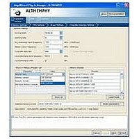
Chapter 3: Parameter Settings
DDR3 SDRAM Controller with ALTMEMPHY Parameter Settings
Table 3–8. Controller Settings (Part 1 of 3)
December 2010 Altera Corporation
Controller architecture
Enable self-refresh controls
Enable power down controls
Enable auto power down
Auto power down cycles
Enable user auto-refresh
controls
Enable auto-precharge
control
Local-to-memory address
mapping
Command queue look-ahead
depth
Parameter
Controller Architecture
HPC II
HPC II
HPC II
HPC II
Both
Both
HPC
HPC
—
Specifies the controller architecture.
Turn on to enable the controller to allow you to have control on
when to place the external memory device in self-refresh mode,
refer to
(HPC II).
Turn on to enable the controller to allow you to have control on
when to place the external memory device in power-down mode.
Turn on to enable the controller to automatically place the
external memory device in power-down mode after a specified
number of idle controller clock cycles is observed in the
controller. You can specify the number of idle cycles after which
the controller powers down the memory in the Auto Power
Down Cycles field, refer to
Programmable Time-Out” on page
Determines the desired number of idle controller clock cycles
before the controller places the external memory device in a
power-down mode. The legal range is 1 to 65,535.
The auto power-down mode is disabled if you set the value to 0
clock cycles.
Turn on to enable the controller to allow you to issue a single
refresh.
Turn on to enable the auto-precharge control on the controller
top level. Asserting the auto-precharge control signal while
requesting a read or write burst allows you to specify whether or
not the controller should close (auto-precharge) the current
opened page at the end of the read or write burst.
Allows you to control the mapping between the address bits on
the Avalon interface and the chip, row, bank, and column bits on
the memory interface.
If your application issues bursts that are greater than the
column size of the memory device, choose the
Chip-Row-Bank-Column option. This option allows the
controller to use its look-ahead bank management feature to
hide the effect of changing the currently open row when the
burst reaches the end of the column.
On the other hand, if your application has several masters that
each use separate areas of memory, choose the
Chip-Bank-Row-Column option. This option allows you to use
the top address bits to allocate a physical bank in the memory to
each master. The physical bank allocation avoids different
masters accessing the same bank which is likely to cause
inefficiency, as the controller must then open and close rows in
the same bank.
Specifies a command queue look-ahead depth value to control
the number of read or write requests the look-ahead bank
management logic examines, refer to
page
7–4.
Section II. DDR3 SDRAM Controller with ALTMEMPHY IP User Guide
“User-Controlled Self-Refresh Logic” on page 7–8
External Memory Interface Handbook Volume 3
Description
“Automatic Power-Down with
7–7.
“Command Queue” on
3–15
Related parts for IPR-HPMCII
Image
Part Number
Description
Manufacturer
Datasheet
Request
R

Part Number:
Description:
IP NIOS II MEGACORE RENEW
Manufacturer:
Altera
Datasheet:
Part Number:
Description:
IP CORE Renewal Of IP-XAUIPCS
Manufacturer:
Altera
Datasheet:

Part Number:
Description:
IP CORE Renewal Of IP-10GETHERNET
Manufacturer:
Altera
Datasheet:
Part Number:
Description:
IP CORE Renewal Of IP-ASI
Manufacturer:
Altera
Datasheet:

Part Number:
Description:
IP CORE Renewal Of IP-CIC
Manufacturer:
Altera
Datasheet:

Part Number:
Description:
IP CORE Renewal Of IP-CRC
Manufacturer:
Altera
Datasheet:
Part Number:
Description:
IP CORE Renewal Of IP-ED8B10B
Manufacturer:
Altera
Datasheet:

Part Number:
Description:
CPLD, EP610 Family, ECMOS Process, 300 Gates, 16 Macro Cells, 16 Reg., 16 User I/Os, 5V Supply, 35 Speed Grade, 24DIP
Manufacturer:
Altera Corporation
Datasheet:
Part Number:
Description:
CPLD, EP610 Family, ECMOS Process, 300 Gates, 16 Macro Cells, 16 Reg., 16 User I/Os, 5V Supply, 15 Speed Grade, 24DIP
Manufacturer:
Altera Corporation
Datasheet:
Part Number:
Description:
Manufacturer:
Altera Corporation
Datasheet: