MPC8544VTALF Freescale Semiconductor, MPC8544VTALF Datasheet - Page 1172
MPC8544VTALF
Manufacturer Part Number
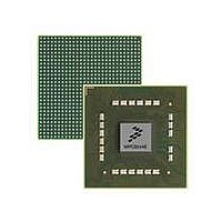
MPC8544VTALF
Description
MPU POWERQUICC III 783-PBGA
Manufacturer
Freescale Semiconductor
Datasheets
1.MPC8544VTALF.pdf
(117 pages)
2.MPC8544VTALF.pdf
(2 pages)
3.MPC8544VTALF.pdf
(1340 pages)
Specifications of MPC8544VTALF
Processor Type
MPC85xx PowerQUICC III 32-Bit
Speed
667MHz
Voltage
1V
Mounting Type
Surface Mount
Package / Case
783-FCPBGA
Processor Series
MPC85xx
Core
e500
Data Bus Width
32 bit
Maximum Clock Frequency
667 MHz
Maximum Operating Temperature
+ 105 C
Mounting Style
SMD/SMT
Data Ram Size
32 KB
I/o Voltage
1.8 V, 3.3 V
Interface Type
I2C, HSSI, DUART
Minimum Operating Temperature
0 C
Lead Free Status / RoHS Status
Lead free / RoHS Compliant
Features
-
Lead Free Status / Rohs Status
Lead free / RoHS Compliant
Available stocks
Company
Part Number
Manufacturer
Quantity
Price
Company:

Part Number:
MPC8544VTALF
Manufacturer:
Freescale Semiconductor
Quantity:
10 000
Company:
Part Number:
MPC8544VTALFA
Manufacturer:
Freescale Semiconductor
Quantity:
10 000


Global Utilities
19.4.1.2
The PORBMSR, shown in
mode settings (described in
Configuration,”
Expresses host/agent mode (described in
For more information about the PCI configurations, see
(PBFR).” Figure 19-5
19-6
10–11
Bits
Offset 0xE_0004
1–4
5–7
8–9
Reset
12
0
W
R BCFG
ROM_LOC Location of boot ROM. This field reflects the values on cfg_rom_loc[0:2] at the negation of HRESET.
BSCFG
Name
BCFG
n
0
—
—
—
POR Boot Mode Status Register (PORBMSR)
MPC8544E PowerQUICC III Integrated Host Processor Family Reference Manual, Rev. 1
1
0 0 0 0 n
and
—
CPU boot configuration
0 The CPU is prevented from booting until configuration by an external master is complete.
1 The CPU is allowed to start fetching boot code.
Reserved
000 PCI
001 DDR SDRAM
010 PCI Express 2
011 PCI Express 3
100 PCI Express 1
101 Local bus GPCM: 8-bit
110 Local bus GPCM:16-bit
111 Local bus GPCM: 32-bit
Reserved
Boot sequencer configuration
00 Reserved
01 Boot sequencer enabled with normal I
10 Boot sequencer enabled with extended I
11 Boot sequencer disabled
Reserved
Section 4.4.3.8, “Boot Sequencer
4
ROM_LOC
describes the bit settings of the PORBMSR.
5
Figure 19-2. POR Boot Mode Status Register (PORBMSR)
n
Figure
Section 4.4.3.4, “Boot ROM Location,” Section 4.4.3.7, “CPU Boot
n 0 0 n
7
Table 19-5. PORBMSR Field Descriptions
8 9 10
—
19-2, reports setting of the POR configuration pins that control the boot
BSCFG —
11
n
Section 4.4.3.5, “Host/Agent
12
0
13
n
2
C addressing
Configuration”) and the default settings of PCI/PCI
2
C addressing
HA
Description
n
Section 17.3.2.19, “PCI Bus Function Register
15
n
16
0 0 0 0 0 0 0 0 0 0 0 0 0 0 0 0
Configuration”).
Freescale Semiconductor
—
Access: Read Only
31
Related parts for MPC8544VTALF
Image
Part Number
Description
Manufacturer
Datasheet
Request
R

Part Number:
Description:
Manufacturer:
Freescale Semiconductor, Inc
Datasheet:
Part Number:
Description:
Manufacturer:
Freescale Semiconductor, Inc
Datasheet:
Part Number:
Description:
Manufacturer:
Freescale Semiconductor, Inc
Datasheet:
Part Number:
Description:
Manufacturer:
Freescale Semiconductor, Inc
Datasheet:
Part Number:
Description:
Manufacturer:
Freescale Semiconductor, Inc
Datasheet:
Part Number:
Description:
Manufacturer:
Freescale Semiconductor, Inc
Datasheet:
Part Number:
Description:
Manufacturer:
Freescale Semiconductor, Inc
Datasheet:
Part Number:
Description:
Manufacturer:
Freescale Semiconductor, Inc
Datasheet:
Part Number:
Description:
Manufacturer:
Freescale Semiconductor, Inc
Datasheet:
Part Number:
Description:
Manufacturer:
Freescale Semiconductor, Inc
Datasheet:
Part Number:
Description:
Manufacturer:
Freescale Semiconductor, Inc
Datasheet:
Part Number:
Description:
Manufacturer:
Freescale Semiconductor, Inc
Datasheet:
Part Number:
Description:
Manufacturer:
Freescale Semiconductor, Inc
Datasheet:
Part Number:
Description:
Manufacturer:
Freescale Semiconductor, Inc
Datasheet:
Part Number:
Description:
Manufacturer:
Freescale Semiconductor, Inc
Datasheet: