MPC8544VTALF Freescale Semiconductor, MPC8544VTALF Datasheet - Page 26
MPC8544VTALF
Manufacturer Part Number
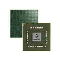
MPC8544VTALF
Description
MPU POWERQUICC III 783-PBGA
Manufacturer
Freescale Semiconductor
Datasheets
1.MPC8544VTALF.pdf
(117 pages)
2.MPC8544VTALF.pdf
(2 pages)
3.MPC8544VTALF.pdf
(1340 pages)
Specifications of MPC8544VTALF
Processor Type
MPC85xx PowerQUICC III 32-Bit
Speed
667MHz
Voltage
1V
Mounting Type
Surface Mount
Package / Case
783-FCPBGA
Processor Series
MPC85xx
Core
e500
Data Bus Width
32 bit
Maximum Clock Frequency
667 MHz
Maximum Operating Temperature
+ 105 C
Mounting Style
SMD/SMT
Data Ram Size
32 KB
I/o Voltage
1.8 V, 3.3 V
Interface Type
I2C, HSSI, DUART
Minimum Operating Temperature
0 C
Lead Free Status / RoHS Status
Lead free / RoHS Compliant
Features
-
Lead Free Status / Rohs Status
Lead free / RoHS Compliant
Available stocks
Company
Part Number
Manufacturer
Quantity
Price
Company:

Part Number:
MPC8544VTALF
Manufacturer:
Freescale Semiconductor
Quantity:
10 000
Company:
Part Number:
MPC8544VTALFA
Manufacturer:
Freescale Semiconductor
Quantity:
10 000


Paragraph
Number
14.4.4.4.9
14.4.4.4.10
14.4.4.5
14.4.4.6
14.4.4.7
14.5
14.5.1
14.5.1.1
14.5.1.2
14.5.1.3
14.5.1.4
14.5.2
14.5.2.1
14.5.2.2
14.5.2.3
14.5.2.4
14.5.3
14.5.4
14.5.4.1
14.5.4.2
14.5.4.3
14.5.4.3.1
14.5.4.3.2
14.5.4.3.3
14.5.4.3.4
14.5.4.3.5
14.5.4.3.6
14.5.4.3.7
14.5.4.3.8
14.5.4.4
14.5.5
14.5.6
14.5.6.1
14.5.6.1.1
14.5.6.1.2
14.5.6.1.3
14.5.6.1.4
14.5.6.2
14.5.6.2.1
14.5.6.2.2
14.5.6.2.3
xxvi
MPC8544E PowerQUICC III Integrated Host Processor Family Reference Manual, Rev. 1
Initialization/Application Information ......................................................................... 14-79
Interfacing to Peripherals......................................................................................... 14-79
Bus Turnaround ....................................................................................................... 14-82
Interface to Different Port-Size Devices.................................................................. 14-83
Interfacing to SDRAM............................................................................................. 14-85
Interfacing to ZBT SRAM....................................................................................... 14-96
Interfacing to DSP Host Ports.................................................................................. 14-98
Synchronous Sampling of LUPWAIT for Early Transfer Acknowledge ............ 14-72
Extended Hold Time on Read Accesses .............................................................. 14-73
Memory System Interface Example Using UPM ................................................ 14-73
Multiplexed Address/Data Bus and Non-Multiplexed Address Signals ............. 14-79
Peripheral Hierarchy on the Local Bus................................................................ 14-80
Peripheral Hierarchy on the Local Bus for Very High Bus Speeds..................... 14-80
GPCM Timings.................................................................................................... 14-81
Address Phase After Previous Read .................................................................... 14-82
Read Data Phase After Address Phase ................................................................ 14-82
Read-Modify-Write Cycle for Parity Protected Memory Banks ......................... 14-83
UPM Cycles with Additional Address Phases..................................................... 14-83
Basic SDRAM Capabilities of the Local Bus...................................................... 14-85
Maximum Amount of SDRAM Supported.......................................................... 14-86
SDRAM Machine Limitations............................................................................. 14-87
Parity Support for SDRAM ................................................................................. 14-95
Interfacing to MSC8101 HDI16 .......................................................................... 14-98
Interfacing to MSC8102 DSI............................................................................. 14-102
LGPL[0:5] Signal Negation (LAST) ............................................................... 14-71
Wait Mechanism (WAEN) ............................................................................... 14-71
Analysis of Maximum Row Number Due to Bank Select Multiplexing......... 14-87
Bank Select Signals ......................................................................................... 14-87
128-Mbyte SDRAM ........................................................................................ 14-88
256-Mbyte SDRAM ........................................................................................ 14-90
512-Mbyte SDRAM ........................................................................................ 14-90
Power-Down Mode.......................................................................................... 14-91
Self-Refresh ..................................................................................................... 14-92
SDRAM Timing .............................................................................................. 14-93
HDI16 Peripherals ........................................................................................... 14-98
Physical Interconnections ................................................................................ 14-99
Supporting Burst Transfers............................................................................ 14-101
Host 60x Bus: HDI16 Peripheral Interface Hardware Timings..................... 14-101
DSI in Asynchronous SRAM-Like Mode ..................................................... 14-102
DSI in Synchronous Mode ............................................................................ 14-105
Broadcast Accesses.........................................................................................14-111
Contents
Title
Freescale Semiconductor
Number
Page
Related parts for MPC8544VTALF
Image
Part Number
Description
Manufacturer
Datasheet
Request
R

Part Number:
Description:
Manufacturer:
Freescale Semiconductor, Inc
Datasheet:
Part Number:
Description:
Manufacturer:
Freescale Semiconductor, Inc
Datasheet:
Part Number:
Description:
Manufacturer:
Freescale Semiconductor, Inc
Datasheet:
Part Number:
Description:
Manufacturer:
Freescale Semiconductor, Inc
Datasheet:
Part Number:
Description:
Manufacturer:
Freescale Semiconductor, Inc
Datasheet:
Part Number:
Description:
Manufacturer:
Freescale Semiconductor, Inc
Datasheet:
Part Number:
Description:
Manufacturer:
Freescale Semiconductor, Inc
Datasheet:
Part Number:
Description:
Manufacturer:
Freescale Semiconductor, Inc
Datasheet:
Part Number:
Description:
Manufacturer:
Freescale Semiconductor, Inc
Datasheet:
Part Number:
Description:
Manufacturer:
Freescale Semiconductor, Inc
Datasheet:
Part Number:
Description:
Manufacturer:
Freescale Semiconductor, Inc
Datasheet:
Part Number:
Description:
Manufacturer:
Freescale Semiconductor, Inc
Datasheet:
Part Number:
Description:
Manufacturer:
Freescale Semiconductor, Inc
Datasheet:
Part Number:
Description:
Manufacturer:
Freescale Semiconductor, Inc
Datasheet:
Part Number:
Description:
Manufacturer:
Freescale Semiconductor, Inc
Datasheet: