MPC8544VTALF Freescale Semiconductor, MPC8544VTALF Datasheet - Page 447
MPC8544VTALF
Manufacturer Part Number
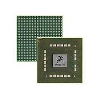
MPC8544VTALF
Description
MPU POWERQUICC III 783-PBGA
Manufacturer
Freescale Semiconductor
Datasheets
1.MPC8544VTALF.pdf
(117 pages)
2.MPC8544VTALF.pdf
(2 pages)
3.MPC8544VTALF.pdf
(1340 pages)
Specifications of MPC8544VTALF
Processor Type
MPC85xx PowerQUICC III 32-Bit
Speed
667MHz
Voltage
1V
Mounting Type
Surface Mount
Package / Case
783-FCPBGA
Processor Series
MPC85xx
Core
e500
Data Bus Width
32 bit
Maximum Clock Frequency
667 MHz
Maximum Operating Temperature
+ 105 C
Mounting Style
SMD/SMT
Data Ram Size
32 KB
I/o Voltage
1.8 V, 3.3 V
Interface Type
I2C, HSSI, DUART
Minimum Operating Temperature
0 C
Lead Free Status / RoHS Status
Lead free / RoHS Compliant
Features
-
Lead Free Status / Rohs Status
Lead free / RoHS Compliant
Available stocks
Company
Part Number
Manufacturer
Quantity
Price
Company:

Part Number:
MPC8544VTALF
Manufacturer:
Freescale Semiconductor
Quantity:
10 000
Company:
Part Number:
MPC8544VTALFA
Manufacturer:
Freescale Semiconductor
Quantity:
10 000


processor’s task priority register, the interrupt router asserts the internal interrupt signal (int) to indicate an
interrupt request to the processor. This causes the processor to vector to the external interrupt handler.
The interrupt handler executing on the processor should then acknowledge the interrupt by explicitly
reading IACK (at which point the interrupt is considered to be in-service). The PIC unit interprets this read
as an interrupt acknowledge (IACK) cycle; in response, the PIC unit returns the vector associated with the
interrupt source to the interrupt handler routine. The handler can further vector to different branches of
interrupt handling accordingly.
Note that reading IACK also negates the interrupt signal to the processor. See
Interrupt Acknowledge Register (IACK),”
Freescale Semiconductor
1
2
3
programmable through
If cint or IRQ_OUT is the destination, EIVPR n [S] must be set to configure the source as level sensitive.
If multiple destination register bits are set, PIC behavior is undefined.
Although setting CI n directs the interrupt request to the critical interrupt output ( cint0 / cint1 ), integrated logic may
connect this signal to a different interrupt input to the core.
PIC Configuration
x VPR n [PRIORITY]
x VPR n [VECTOR]
Status Registers
(defined by the
IACK[VECTOR]
CTPR[TASKP]
specification)
x VPR n [MSK]
Interrupt sources
OpenPIC
x VPR n [A]
the PIC
MPC8544E PowerQUICC III Integrated Host Processor Family Reference Manual, Rev. 1
x VPR n [PRIORITY]
Read IACK
Clear MSR[EE]
. . .
Write EOI
rfi
Interrupt Service Routine
Interprocessor
Figure 10-48. PIC Interrupt Processing Flow Diagram
Global Timer
CTPR[TASKP]
greater than
interrupt pending register (IPR )
int0 (if x IDR n [P0] = 1)
int1 (if x IDR n [P1] = 1)
If true
mask register
Destination:
/ Retrieves vector (IACK[VECTOR]), negates int,
/ puts interrupt in service (sets ISR bit)
/ Enables recognition of int for higher priority interrupt
/ Clears ISR bit to remove interrupt from service
/ Returns control to and restores state of interrupted process
for more details.
If true
interrupt request register (IRR)
Message Shared
Message
External
Internal
Interrupt Selector
Interrupt Router
2
int0 (if x VPR n [P0] = 1)
int1 (if x VPR n [P1] = 1)
Core
Level sensitive only
in-service register (ISR)
x IDR n [CI n ] = 1
x IDR n [EP] = 1
Highest priority interrupt in IPR (non
masked) and ISR is chosen.
If x VPR n [PRIORITY] > CTPR[TASKP], int is
asserted and x VPR n [VECTOR] is copied to
IACK[VECTOR]
Section 10.3.8.4, “Processor
2
Programmable Interrupt Controller
cint0 (if x IDR n [CI0] = 1)
cint1 (if x IDR n [CI1] = 1)
IRQ_OUT
Interrupt Output
3
10-49
Related parts for MPC8544VTALF
Image
Part Number
Description
Manufacturer
Datasheet
Request
R

Part Number:
Description:
Manufacturer:
Freescale Semiconductor, Inc
Datasheet:
Part Number:
Description:
Manufacturer:
Freescale Semiconductor, Inc
Datasheet:
Part Number:
Description:
Manufacturer:
Freescale Semiconductor, Inc
Datasheet:
Part Number:
Description:
Manufacturer:
Freescale Semiconductor, Inc
Datasheet:
Part Number:
Description:
Manufacturer:
Freescale Semiconductor, Inc
Datasheet:
Part Number:
Description:
Manufacturer:
Freescale Semiconductor, Inc
Datasheet:
Part Number:
Description:
Manufacturer:
Freescale Semiconductor, Inc
Datasheet:
Part Number:
Description:
Manufacturer:
Freescale Semiconductor, Inc
Datasheet:
Part Number:
Description:
Manufacturer:
Freescale Semiconductor, Inc
Datasheet:
Part Number:
Description:
Manufacturer:
Freescale Semiconductor, Inc
Datasheet:
Part Number:
Description:
Manufacturer:
Freescale Semiconductor, Inc
Datasheet:
Part Number:
Description:
Manufacturer:
Freescale Semiconductor, Inc
Datasheet:
Part Number:
Description:
Manufacturer:
Freescale Semiconductor, Inc
Datasheet:
Part Number:
Description:
Manufacturer:
Freescale Semiconductor, Inc
Datasheet:
Part Number:
Description:
Manufacturer:
Freescale Semiconductor, Inc
Datasheet: