MPC8544VTALF Freescale Semiconductor, MPC8544VTALF Datasheet - Page 684
MPC8544VTALF
Manufacturer Part Number
MPC8544VTALF
Description
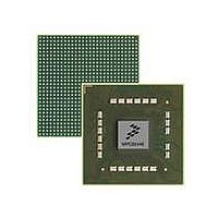
MPU POWERQUICC III 783-PBGA
Manufacturer
Freescale Semiconductor
Datasheets
1.MPC8544VTALF.pdf
(117 pages)
2.MPC8544VTALF.pdf
(2 pages)
3.MPC8544VTALF.pdf
(1340 pages)
Specifications of MPC8544VTALF
Processor Type
MPC85xx PowerQUICC III 32-Bit
Speed
667MHz
Voltage
1V
Mounting Type
Surface Mount
Package / Case
783-FCPBGA
Processor Series
MPC85xx
Core
e500
Data Bus Width
32 bit
Maximum Clock Frequency
667 MHz
Maximum Operating Temperature
+ 105 C
Mounting Style
SMD/SMT
Data Ram Size
32 KB
I/o Voltage
1.8 V, 3.3 V
Interface Type
I2C, HSSI, DUART
Minimum Operating Temperature
0 C
Lead Free Status / RoHS Status
Lead free / RoHS Compliant
Features
-
Lead Free Status / Rohs Status
Lead free / RoHS Compliant
Available stocks
Company
Part Number
Manufacturer
Quantity
Price
Company:

Part Number:
MPC8544VTALF
Manufacturer:
Freescale Semiconductor
Quantity:
10 000
Company:
Part Number:
MPC8544VTALFA
Manufacturer:
Freescale Semiconductor
Quantity:
10 000


Local Bus Controller
14.4.4.3
RAM word fields specify the value of the various external signals at a granularity of up to four values for
each bus clock cycle. The signal timing generator causes external signals to behave according to timing
specified in the current RAM word. Each bit in the RAM word relating to LCSn and LBS timing specifies
the value of the corresponding external signal at each quarter phase of the bus clock.
The division of UPM bus cycles into phases is shown in
14.4.4.4
The RAM array for each UPM is 64 locations deep and 32 bits wide, as shown in
at the bottom of the figure are UPM outputs. The selected LCSn is for the bank that matches the current
address. The selected LBS is for the byte lanes read or written by the access.
14-64
9. Read/check MxMR[MAD]. If incremented, then the previous dummy read transaction is
10. Read MDR.
Clock Phases
T1, T2, T3, T4
completed; proceed to step 10. Repeat step 9 until incremented.
Current Bank
LCLK
T1
T2
T3
T4
MPC8544E PowerQUICC III Integrated Host Processor Family Reference Manual, Rev. 1
UPM Signal Timing
RAM Array
LCS[0:7]
CS Line
Selector
Figure 14-57. RAM Array and Signal Generation
LGPL0
Figure 14-56. UPM Clock Scheme
External Signals Timing Generator
LGPL1
RAM Array
LGPL2 LGPL3 LGPL4 LGPL5
32 Bits
Figure
14-56.
Byte Select
LBS[0:3]
64 Deep
Figure
Logic
BRn[PS], LA[30,31]
Freescale Semiconductor
14-57. The signals
Related parts for MPC8544VTALF
Image
Part Number
Description
Manufacturer
Datasheet
Request
R

Part Number:
Description:
Manufacturer:
Freescale Semiconductor, Inc
Datasheet:
Part Number:
Description:
Manufacturer:
Freescale Semiconductor, Inc
Datasheet:
Part Number:
Description:
Manufacturer:
Freescale Semiconductor, Inc
Datasheet:
Part Number:
Description:
Manufacturer:
Freescale Semiconductor, Inc
Datasheet:
Part Number:
Description:
Manufacturer:
Freescale Semiconductor, Inc
Datasheet:
Part Number:
Description:
Manufacturer:
Freescale Semiconductor, Inc
Datasheet:
Part Number:
Description:
Manufacturer:
Freescale Semiconductor, Inc
Datasheet:
Part Number:
Description:
Manufacturer:
Freescale Semiconductor, Inc
Datasheet:
Part Number:
Description:
Manufacturer:
Freescale Semiconductor, Inc
Datasheet:
Part Number:
Description:
Manufacturer:
Freescale Semiconductor, Inc
Datasheet:
Part Number:
Description:
Manufacturer:
Freescale Semiconductor, Inc
Datasheet:
Part Number:
Description:
Manufacturer:
Freescale Semiconductor, Inc
Datasheet:
Part Number:
Description:
Manufacturer:
Freescale Semiconductor, Inc
Datasheet:
Part Number:
Description:
Manufacturer:
Freescale Semiconductor, Inc
Datasheet:
Part Number:
Description:
Manufacturer:
Freescale Semiconductor, Inc
Datasheet: