MPC8544VTALF Freescale Semiconductor, MPC8544VTALF Datasheet - Page 404
MPC8544VTALF
Manufacturer Part Number
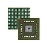
MPC8544VTALF
Description
MPU POWERQUICC III 783-PBGA
Manufacturer
Freescale Semiconductor
Datasheets
1.MPC8544VTALF.pdf
(117 pages)
2.MPC8544VTALF.pdf
(2 pages)
3.MPC8544VTALF.pdf
(1340 pages)
Specifications of MPC8544VTALF
Processor Type
MPC85xx PowerQUICC III 32-Bit
Speed
667MHz
Voltage
1V
Mounting Type
Surface Mount
Package / Case
783-FCPBGA
Processor Series
MPC85xx
Core
e500
Data Bus Width
32 bit
Maximum Clock Frequency
667 MHz
Maximum Operating Temperature
+ 105 C
Mounting Style
SMD/SMT
Data Ram Size
32 KB
I/o Voltage
1.8 V, 3.3 V
Interface Type
I2C, HSSI, DUART
Minimum Operating Temperature
0 C
Lead Free Status / RoHS Status
Lead free / RoHS Compliant
Features
-
Lead Free Status / Rohs Status
Lead free / RoHS Compliant
Available stocks
Company
Part Number
Manufacturer
Quantity
Price
Company:

Part Number:
MPC8544VTALF
Manufacturer:
Freescale Semiconductor
Quantity:
10 000
Company:
Part Number:
MPC8544VTALFA
Manufacturer:
Freescale Semiconductor
Quantity:
10 000


Programmable Interrupt Controller
10.1.5.1
When an interrupt request is delivered to the PIC, the corresponding interrupt destination register is checked
to determine where the request should be routed, as follows:
10.1.5.2
Table 10-3
interrupts generated by the PIC unit.
10-6
Internal Interrupt
•
•
•
•
•
Number
Message registers—From inside the PIC. Triggered on register write, cleared on read. Used for
inter-process communication.
Shared message signaled interrupt registers—From within the PIC. Triggered on register write;
cleared on read.
If xIDRn[EP] = 1 (and all other destination bits are zero), the interrupt is routed off-chip to the
external signal. Or if the PCI Express controller is in EP mode and automatically generates a PCI
Express MSI transaction. See
If xIDR[CI] is set (and all other destination bits are zero), the interrupt is routed to cint.
If xIDRn[P0] is set (and all other destination bits are zero) the interrupt is routed to int0. Setting
xIDRn[P1] likewise routs the interrupt to int1 In this case, the interrupt is latched by the interrupt
pending register (IPR) and the interrupt flow is as described in
Control.”
10
11
12
13
0
1
2
3
4
5
6
7
8
9
shows the assignments of the internal interrupt sources. Note that this list does not include the
MPC8544E PowerQUICC III Integrated Host Processor Family Reference Manual, Rev. 1
Interrupt Routing—Mixed Mode
Internal Interrupt Sources
L2 cache
ECM
DDR DRAM
LBC
DMA channel 0
DMA channel 1
DMA channel 2
DMA channel 3
PCI
PCI Express 2
PCI Express1
PCI Express 3
Reserved
eTSEC1 transmit
Interrupt Source
Table 10-3. Internal Interrupt Sources
Section 18.4.2.1.2, “Hardware MSI
Internal Interrupt
Number
24
25
26
27
28
29
30
31
32
33
34
35
36
37
Reserved
Reserved
DUART
I
Performance monitor
Security channel
Reserved
Reserved
Reserved
Reserved
Reserved
Reserved
Reserved
Reserved
2
1
C controllers
Section 10.4.1, “Flow of Interrupt
Generation.”
Interrupt Source
Freescale Semiconductor
Related parts for MPC8544VTALF
Image
Part Number
Description
Manufacturer
Datasheet
Request
R

Part Number:
Description:
Manufacturer:
Freescale Semiconductor, Inc
Datasheet:
Part Number:
Description:
Manufacturer:
Freescale Semiconductor, Inc
Datasheet:
Part Number:
Description:
Manufacturer:
Freescale Semiconductor, Inc
Datasheet:
Part Number:
Description:
Manufacturer:
Freescale Semiconductor, Inc
Datasheet:
Part Number:
Description:
Manufacturer:
Freescale Semiconductor, Inc
Datasheet:
Part Number:
Description:
Manufacturer:
Freescale Semiconductor, Inc
Datasheet:
Part Number:
Description:
Manufacturer:
Freescale Semiconductor, Inc
Datasheet:
Part Number:
Description:
Manufacturer:
Freescale Semiconductor, Inc
Datasheet:
Part Number:
Description:
Manufacturer:
Freescale Semiconductor, Inc
Datasheet:
Part Number:
Description:
Manufacturer:
Freescale Semiconductor, Inc
Datasheet:
Part Number:
Description:
Manufacturer:
Freescale Semiconductor, Inc
Datasheet:
Part Number:
Description:
Manufacturer:
Freescale Semiconductor, Inc
Datasheet:
Part Number:
Description:
Manufacturer:
Freescale Semiconductor, Inc
Datasheet:
Part Number:
Description:
Manufacturer:
Freescale Semiconductor, Inc
Datasheet:
Part Number:
Description:
Manufacturer:
Freescale Semiconductor, Inc
Datasheet: