C8051F930-TB Silicon Laboratories Inc, C8051F930-TB Datasheet - Page 189
C8051F930-TB
Manufacturer Part Number
C8051F930-TB
Description
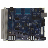
BOARD TARGET/PROTO W/C8051F930
Manufacturer
Silicon Laboratories Inc
Type
MCUr
Specifications of C8051F930-TB
Contents
Board
Processor To Be Evaluated
C8051F930
Processor Series
C8051F9xx
Data Bus Width
8 bit
Interface Type
I2C, UART, SPI
Maximum Operating Temperature
+ 85 C
Minimum Operating Temperature
- 40 C
Operating Supply Voltage
0.9 V to 3.6 V
Lead Free Status / RoHS Status
Lead free / RoHS Compliant
For Use With/related Products
C8051F930
Lead Free Status / Rohs Status
Lead free / RoHS Compliant
Other names
336-1472


Important Note on External Crystals: Crystal oscillator circuits are quite sensitive to PCB layout. The
crystal should be placed as close as possible to the XTAL pins on the device. The traces should be as
short as possible and shielded with ground plane from any other traces which could introduce noise or
interference.
When using an external crystal, the external oscillator drive circuit must be configured by software for
Crystal Oscillator Mode or Crystal Oscillator Mode with divide by 2 stage. The divide by 2 stage ensures
that the clock derived from the external oscillator has a duty cycle of 50%. The External Oscillator
Frequency Control value (XFCN) must also be specified based on the crystal frequency. The selection
should be based on Table 19.1. For example, a 25 MHz crystal requires an XFCN setting of 111b.
When the crystal oscillator is first enabled, the external oscillator valid detector allows software to
determine when the external system clock has stabilized. Switching to the external oscillator before the
crystal oscillator has stabilized can result in unpredictable behavior. The recommended procedure for
starting the crystal is:
XFCN
000
001
010
100
101
011
110
111
1. Configure XTAL1 and XTAL2 for analog I/O and disable the digital output drivers.
2. Configure and enable the external oscillator.
3. Poll for XTLVLD > 1.
4. Switch the system clock to the external oscillator.
Table 19.1. Recommended XFCN Settings for Crystal Mode
155 kHz f 415 kHz
415 kHz f 1.1 MHz
1.1 MHz f 3.1 MHz
3.1 MHz f 8.2 MHz
8.2 MHz f 25 MHz
58 kHz f 155 kHz
20 kHz f 58 kHz
Crystal Frequency
Figure 19.2. 25 MHz External Crystal Example
f 20 kHz
25 MHz
15 pF
15 pF
Rev. 1.1
Bias Current
C8051F93x-C8051F92x
120 µA
550 µA
2.6 mA
0.5 µA
1.5 µA
4.8 µA
14 µA
40 µA
10 M
XTAL1
XTAL2
Typical Supply Current
3.0 µA, f = 32.768 kHz
4.8 µA, f = 32.768 kHz
9.6 µA, f = 32.768 kHz
193 µA, f = 400 kHz
3.9 mA, f = 25 MHz
28 µA, f = 400 kHz
71 µA, f = 400 kHz
940 µA, f = 8 MHz
(VDD = 2.4 V)
189
Related parts for C8051F930-TB
Image
Part Number
Description
Manufacturer
Datasheet
Request
R

Part Number:
Description:
SMD/C°/SINGLE-ENDED OUTPUT SILICON OSCILLATOR
Manufacturer:
Silicon Laboratories Inc
Part Number:
Description:
Manufacturer:
Silicon Laboratories Inc
Datasheet:
Part Number:
Description:
N/A N/A/SI4010 AES KEYFOB DEMO WITH LCD RX
Manufacturer:
Silicon Laboratories Inc
Datasheet:
Part Number:
Description:
N/A N/A/SI4010 SIMPLIFIED KEY FOB DEMO WITH LED RX
Manufacturer:
Silicon Laboratories Inc
Datasheet:
Part Number:
Description:
N/A/-40 TO 85 OC/EZLINK MODULE; F930/4432 HIGH BAND (REV E/B1)
Manufacturer:
Silicon Laboratories Inc
Part Number:
Description:
EZLink Module; F930/4432 Low Band (rev e/B1)
Manufacturer:
Silicon Laboratories Inc
Part Number:
Description:
I°/4460 10 DBM RADIO TEST CARD 434 MHZ
Manufacturer:
Silicon Laboratories Inc
Part Number:
Description:
I°/4461 14 DBM RADIO TEST CARD 868 MHZ
Manufacturer:
Silicon Laboratories Inc
Part Number:
Description:
I°/4463 20 DBM RFSWITCH RADIO TEST CARD 460 MHZ
Manufacturer:
Silicon Laboratories Inc
Part Number:
Description:
I°/4463 20 DBM RADIO TEST CARD 868 MHZ
Manufacturer:
Silicon Laboratories Inc
Part Number:
Description:
I°/4463 27 DBM RADIO TEST CARD 868 MHZ
Manufacturer:
Silicon Laboratories Inc
Part Number:
Description:
I°/4463 SKYWORKS 30 DBM RADIO TEST CARD 915 MHZ
Manufacturer:
Silicon Laboratories Inc
Part Number:
Description:
N/A N/A/-40 TO 85 OC/4463 RFMD 30 DBM RADIO TEST CARD 915 MHZ
Manufacturer:
Silicon Laboratories Inc
Part Number:
Description:
I°/4463 20 DBM RADIO TEST CARD 169 MHZ
Manufacturer:
Silicon Laboratories Inc