C8051F930-TB Silicon Laboratories Inc, C8051F930-TB Datasheet - Page 6
C8051F930-TB
Manufacturer Part Number
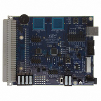
C8051F930-TB
Description
BOARD TARGET/PROTO W/C8051F930
Manufacturer
Silicon Laboratories Inc
Type
MCUr
Specifications of C8051F930-TB
Contents
Board
Processor To Be Evaluated
C8051F930
Processor Series
C8051F9xx
Data Bus Width
8 bit
Interface Type
I2C, UART, SPI
Maximum Operating Temperature
+ 85 C
Minimum Operating Temperature
- 40 C
Operating Supply Voltage
0.9 V to 3.6 V
Lead Free Status / RoHS Status
Lead free / RoHS Compliant
For Use With/related Products
C8051F930
Lead Free Status / Rohs Status
Lead free / RoHS Compliant
Other names
336-1472


C8051F93x-C8051F92x
19. Clocking Sources ................................................................................................. 187
20. SmaRTClock (Real Time Clock) .......................................................................... 196
21. Port Input/Output.................................................................................................. 212
6
18.8.SmaRTClock (Real Time Clock) Reset .......................................................... 185
18.9.Software Reset ............................................................................................... 185
19.1.Programmable Precision Internal Oscillator ................................................... 188
19.2.Low Power Internal Oscillator......................................................................... 188
19.3.External Oscillator Drive Circuit...................................................................... 188
19.4.Special Function Registers for Selecting and Configuring the System Clock 193
20.1.SmaRTClock Interface ................................................................................... 197
20.2.SmaRTClock Clocking Sources ..................................................................... 202
20.3.SmaRTClock Timer and Alarm Function ........................................................ 206
21.1.Port I/O Modes of Operation........................................................................... 213
21.2.Assigning Port I/O Pins to Analog and Digital Functions................................ 214
21.3.Priority Crossbar Decoder .............................................................................. 216
21.4.Port Match ...................................................................................................... 222
21.5.Special Function Registers for Accessing and Configuring Port I/O .............. 224
19.3.1.External Crystal Mode............................................................................ 188
19.3.2.External RC Mode.................................................................................. 190
19.3.3.External Capacitor Mode........................................................................ 191
19.3.4.External CMOS Clock Mode .................................................................. 192
20.1.1.SmaRTClock Lock and Key Functions................................................... 197
20.1.2.Using RTC0ADR and RTC0DAT to Access
20.1.3.RTC0ADR Short Strobe Feature............................................................ 198
20.1.4.SmaRTClock Interface Autoread Feature .............................................. 199
20.1.5.RTC0ADR Autoincrement Feature......................................................... 199
20.2.1.Using the SmaRTClock Oscillator with a Crystal or
20.2.2.Using the SmaRTClock Oscillator in Self-Oscillate Mode...................... 202
20.2.3.Programmable Load Capacitance.......................................................... 203
20.2.4.Automatic Gain Control (Crystal Mode Only) and
20.2.5.Missing SmaRTClock Detector .............................................................. 206
20.2.6.SmaRTClock Oscillator Crystal Valid Detector ...................................... 206
20.3.1.Setting and Reading the SmaRTClock Timer Value .............................. 206
20.3.2.Setting a SmaRTClock Alarm ................................................................ 207
20.3.3.Software Considerations for using the SmaRTClock Timer and Alarm . 207
21.1.1.Port Pins Configured for Analog I/O....................................................... 213
21.1.2.Port Pins Configured For Digital I/O....................................................... 213
21.1.3.Interfacing Port I/O to 5 V Logic ............................................................. 214
21.1.4.Increasing Port I/O Drive Strength ......................................................... 214
21.2.1.Assigning Port I/O Pins to Analog Functions ......................................... 214
21.2.2.Assigning Port I/O Pins to Digital Functions........................................... 215
21.2.3.Assigning Port I/O Pins to External Digital Event Capture Functions .... 215
SmaRTClock Internal Registers ............................................................. 198
External CMOS Clock ............................................................................ 202
SmaRTClock Bias Doubling ................................................................... 204
Rev. 1.1
Related parts for C8051F930-TB
Image
Part Number
Description
Manufacturer
Datasheet
Request
R

Part Number:
Description:
SMD/C°/SINGLE-ENDED OUTPUT SILICON OSCILLATOR
Manufacturer:
Silicon Laboratories Inc
Part Number:
Description:
Manufacturer:
Silicon Laboratories Inc
Datasheet:
Part Number:
Description:
N/A N/A/SI4010 AES KEYFOB DEMO WITH LCD RX
Manufacturer:
Silicon Laboratories Inc
Datasheet:
Part Number:
Description:
N/A N/A/SI4010 SIMPLIFIED KEY FOB DEMO WITH LED RX
Manufacturer:
Silicon Laboratories Inc
Datasheet:
Part Number:
Description:
N/A/-40 TO 85 OC/EZLINK MODULE; F930/4432 HIGH BAND (REV E/B1)
Manufacturer:
Silicon Laboratories Inc
Part Number:
Description:
EZLink Module; F930/4432 Low Band (rev e/B1)
Manufacturer:
Silicon Laboratories Inc
Part Number:
Description:
I°/4460 10 DBM RADIO TEST CARD 434 MHZ
Manufacturer:
Silicon Laboratories Inc
Part Number:
Description:
I°/4461 14 DBM RADIO TEST CARD 868 MHZ
Manufacturer:
Silicon Laboratories Inc
Part Number:
Description:
I°/4463 20 DBM RFSWITCH RADIO TEST CARD 460 MHZ
Manufacturer:
Silicon Laboratories Inc
Part Number:
Description:
I°/4463 20 DBM RADIO TEST CARD 868 MHZ
Manufacturer:
Silicon Laboratories Inc
Part Number:
Description:
I°/4463 27 DBM RADIO TEST CARD 868 MHZ
Manufacturer:
Silicon Laboratories Inc
Part Number:
Description:
I°/4463 SKYWORKS 30 DBM RADIO TEST CARD 915 MHZ
Manufacturer:
Silicon Laboratories Inc
Part Number:
Description:
N/A N/A/-40 TO 85 OC/4463 RFMD 30 DBM RADIO TEST CARD 915 MHZ
Manufacturer:
Silicon Laboratories Inc
Part Number:
Description:
I°/4463 20 DBM RADIO TEST CARD 169 MHZ
Manufacturer:
Silicon Laboratories Inc