C8051F930-TB Silicon Laboratories Inc, C8051F930-TB Datasheet - Page 272
C8051F930-TB
Manufacturer Part Number
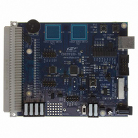
C8051F930-TB
Description
BOARD TARGET/PROTO W/C8051F930
Manufacturer
Silicon Laboratories Inc
Type
MCUr
Specifications of C8051F930-TB
Contents
Board
Processor To Be Evaluated
C8051F930
Processor Series
C8051F9xx
Data Bus Width
8 bit
Interface Type
I2C, UART, SPI
Maximum Operating Temperature
+ 85 C
Minimum Operating Temperature
- 40 C
Operating Supply Voltage
0.9 V to 3.6 V
Lead Free Status / RoHS Status
Lead free / RoHS Compliant
For Use With/related Products
C8051F930
Lead Free Status / Rohs Status
Lead free / RoHS Compliant
Other names
336-1472


C8051F93x-C8051F92x
SFR Definition 24.2. SPInCN: SPI Control
SFR Addresses: SPI0CN = 0xF8, Bit-Addressable; SPI1CN = 0xB0, Bit-Addressable
SFR Pages: SPI0CN = 0x0, SPI1CN = 0x0
272
Name
Reset
Bit
3:2
Type
7
6
5
4
1
0
Bit
NSSnMD[1:0] Slave Select Mode.
RXOVRNn
TXBMTn
WCOLn
MODFn
SPInEN
SPIFn
Name
SPIFn
R/W
7
0
WCOLn MODFn
R/W
6
0
SPIn Interrupt Flag.
This bit is set to logic 1 by hardware at the end of a data transfer. If interrupts are
enabled, setting this bit causes the CPU to vector to the SPIn interrupt service
routine. This bit is not automatically cleared by hardware. It must be cleared by
software.
Write Collision Flag.
This bit is set to logic 1 by hardware (and generates a SPI0 interrupt) to indicate a
write to the SPI0 data register was attempted while a data transfer was in progress.
It must be cleared by software.
Mode Fault Flag.
This bit is set to logic 1 by hardware (and generates a SPI0 interrupt) when a mas-
ter mode collision is detected (NSS is low, MSTEN = 1, and NSSMD[1:0] = 01).
This bit is not automatically cleared by hardware. It must be cleared by software.
Receive Overrun Flag (valid in slave mode only).
This bit is set to logic 1 by hardware (and generates a SPIn interrupt) when the
receive buffer still holds unread data from a previous transfer and the last bit of the
current transfer is shifted into the SPI shift register. This bit is not automatically
cleared by hardware. It must be cleared by software.
Selects between the following NSS operation modes:
(See Section 24.2 and Section 24.3).
00: 3-Wire Slave or 3-Wire Master Mode. NSS signal is not routed to a port pin.
01: 4-Wire Slave or Multi-Master Mode (Default). NSS is an input to the device.
1x: 4-Wire Single-Master Mode. NSS signal is mapped as an output from the
device and will assume the value of NSSMD0.
Transmit Buffer Empty.
This bit will be set to logic 0 when new data has been written to the transmit buffer.
When data in the transmit buffer is transferred to the SPI shift register, this bit will
be set to logic 1, indicating that it is safe to write a new byte to the transmit buffer.
SPIn Enable.
0: SPIn disabled.
1: SPIn enabled.
R/W
5
0
RXOVRNn
R/W
4
0
Rev. 1.1
NSSnMD1
R/W
3
0
Function
NSSnMD0
R/W
2
1
TXBMTn
R
1
1
SPInEN
R/W
0
0
Related parts for C8051F930-TB
Image
Part Number
Description
Manufacturer
Datasheet
Request
R

Part Number:
Description:
SMD/C°/SINGLE-ENDED OUTPUT SILICON OSCILLATOR
Manufacturer:
Silicon Laboratories Inc
Part Number:
Description:
Manufacturer:
Silicon Laboratories Inc
Datasheet:
Part Number:
Description:
N/A N/A/SI4010 AES KEYFOB DEMO WITH LCD RX
Manufacturer:
Silicon Laboratories Inc
Datasheet:
Part Number:
Description:
N/A N/A/SI4010 SIMPLIFIED KEY FOB DEMO WITH LED RX
Manufacturer:
Silicon Laboratories Inc
Datasheet:
Part Number:
Description:
N/A/-40 TO 85 OC/EZLINK MODULE; F930/4432 HIGH BAND (REV E/B1)
Manufacturer:
Silicon Laboratories Inc
Part Number:
Description:
EZLink Module; F930/4432 Low Band (rev e/B1)
Manufacturer:
Silicon Laboratories Inc
Part Number:
Description:
I°/4460 10 DBM RADIO TEST CARD 434 MHZ
Manufacturer:
Silicon Laboratories Inc
Part Number:
Description:
I°/4461 14 DBM RADIO TEST CARD 868 MHZ
Manufacturer:
Silicon Laboratories Inc
Part Number:
Description:
I°/4463 20 DBM RFSWITCH RADIO TEST CARD 460 MHZ
Manufacturer:
Silicon Laboratories Inc
Part Number:
Description:
I°/4463 20 DBM RADIO TEST CARD 868 MHZ
Manufacturer:
Silicon Laboratories Inc
Part Number:
Description:
I°/4463 27 DBM RADIO TEST CARD 868 MHZ
Manufacturer:
Silicon Laboratories Inc
Part Number:
Description:
I°/4463 SKYWORKS 30 DBM RADIO TEST CARD 915 MHZ
Manufacturer:
Silicon Laboratories Inc
Part Number:
Description:
N/A N/A/-40 TO 85 OC/4463 RFMD 30 DBM RADIO TEST CARD 915 MHZ
Manufacturer:
Silicon Laboratories Inc
Part Number:
Description:
I°/4463 20 DBM RADIO TEST CARD 169 MHZ
Manufacturer:
Silicon Laboratories Inc