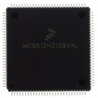
MC9S12HZ128VAL Freescale Semiconductor, MC9S12HZ128VAL Datasheet - Page 281

MC9S12HZ128VAL
Manufacturer Part Number
MC9S12HZ128VAL
Description
IC MCU 16BIT 2K FLASH 112-LQFP
Manufacturer
Freescale Semiconductor
Series
HCS12r
Datasheet
1.MC9S12HZ128CAL.pdf
(692 pages)
Specifications of MC9S12HZ128VAL
Core Processor
HCS12
Core Size
16-Bit
Speed
25MHz
Connectivity
CAN, EBI/EMI, I²C, SCI, SPI
Peripherals
LCD, Motor control PWM, POR, PWM, WDT
Number Of I /o
85
Program Memory Size
128KB (128K x 8)
Program Memory Type
FLASH
Eeprom Size
2K x 8
Ram Size
6K x 8
Voltage - Supply (vcc/vdd)
2.35 V ~ 5.5 V
Data Converters
A/D 16x10b
Oscillator Type
Internal
Operating Temperature
-40°C ~ 105°C
Package / Case
112-LQFP
Processor Series
S12H
Core
HCS12
Data Bus Width
16 bit
Data Ram Size
6 KB
Interface Type
I2C/SCI/SPI
Maximum Clock Frequency
50 MHz
Number Of Programmable I/os
85
Number Of Timers
8
Maximum Operating Temperature
+ 105 C
Mounting Style
SMD/SMT
3rd Party Development Tools
EWHCS12
Minimum Operating Temperature
- 40 C
On-chip Adc
16-ch x 10-bit
Lead Free Status / RoHS Status
Lead free / RoHS Compliant
Available stocks
Company
Part Number
Manufacturer
Quantity
Price
Company:
Part Number:
MC9S12HZ128VAL
Manufacturer:
Freescale Semiconductor
Quantity:
10 000
Part Number:
MC9S12HZ128VAL
Manufacturer:
FREESCALE
Quantity:
20 000
- Current page: 281 of 692
- Download datasheet (4Mb)
value, DUTY, contained in D[10:1] in MCDCx. When a match (output compare between motor controller
timer counter and DUTY) occurs, the PWM output will toggle to a logic high level and will remain at a
logic high level until the motor controller timer counter overflows (reaches the value defined by
P[10:1] – 1 in MCPER). After the motor controller timer counter resets to 0x000, the PWM output will
return to a logic low level. This completes the first half of the PWM period. During the second half of the
PWM period, the PWM output will remain at a logic low level until either the motor controller timer
counter matches the 10-bit PWM duty cycle value, DUTY, contained in D[10:1] in MCDCx if D0 = 0, or
the motor controller timer counter matches the 10-bit PWM duty cycle value + 1 (the value of D[10:1] in
MCDCx is increment by 1 and is compared with the motor controller timer counter value) if D0 = 1 in the
corresponding duty cycle register. When a match occurs, the PWM output will toggle to a logic high level
and will remain at a logic high level until the motor controller timer counter overflows (reaches the value
defined by P[10:1] – 1 in MCPER). After the motor controller timer counter resets to 0x000, the PWM
output will return to a logic low level.
This process will repeat every number of counts of the motor controller timer counter defined by the period
register contents (P[10:0]). If the output is neither set to 0% nor to 100% there will be four edges on the
PWM output per PWM period in this case. Therefore, the PWM output compare function will alternate
between DUTY and DUTY + 1 every half PWM period if D0 in the corresponding duty cycle register is
set to 1. The relationship between the motor controller timer counter clock (f
counter value, and left aligned PWM output if DITH = 1 is shown in
Figure 9-20
dither feature enabled and D0 = 1. Please note: In the following examples, the MCPER value is defined
by the bits P[10:0], which is, if DITH = 1, always an even number.
Freescale Semiconductor
Motor Controller
Motor Controller
Figure 9-18. PWM Output: DITH = 1, MCAM[1:0] = 01, MCDC = 31, MCPER = 200, RECIRC = 0
Timer Counter
Timer Counter
PWM Output
and
The DITH bit must be changed only if the motor controller is disabled (all
channels disabled or period register cleared) to avoid erroneous waveforms.
Clock
Figure 9-21
0
show right aligned and center aligned PWM operation respectively, with
15
100 Counts
MC9S12HZ256 Data Sheet, Rev. 2.05
16
NOTE
1 Period
99
0
15
100 Counts
Figure 9-18
Chapter 9 Motor Controller (MC10B8CV1)
TC
16
), motor controller timer
and
Figure
99
0
9-19.
281
Related parts for MC9S12HZ128VAL
Image
Part Number
Description
Manufacturer
Datasheet
Request
R
Part Number:
Description:
Manufacturer:
Freescale Semiconductor, Inc
Datasheet:
Part Number:
Description:
Manufacturer:
Freescale Semiconductor, Inc
Datasheet:
Part Number:
Description:
Manufacturer:
Freescale Semiconductor, Inc
Datasheet:
Part Number:
Description:
Manufacturer:
Freescale Semiconductor, Inc
Datasheet:
Part Number:
Description:
Manufacturer:
Freescale Semiconductor, Inc
Datasheet:
Part Number:
Description:
Manufacturer:
Freescale Semiconductor, Inc
Datasheet:
Part Number:
Description:
Manufacturer:
Freescale Semiconductor, Inc
Datasheet:
Part Number:
Description:
Manufacturer:
Freescale Semiconductor, Inc
Datasheet:
Part Number:
Description:
Manufacturer:
Freescale Semiconductor, Inc
Datasheet:
Part Number:
Description:
Manufacturer:
Freescale Semiconductor, Inc
Datasheet:
Part Number:
Description:
Manufacturer:
Freescale Semiconductor, Inc
Datasheet:
Part Number:
Description:
Manufacturer:
Freescale Semiconductor, Inc
Datasheet:
Part Number:
Description:
Manufacturer:
Freescale Semiconductor, Inc
Datasheet:
Part Number:
Description:
Manufacturer:
Freescale Semiconductor, Inc
Datasheet:
Part Number:
Description:
Manufacturer:
Freescale Semiconductor, Inc
Datasheet:


