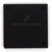
MC9S12HZ128VAL Freescale Semiconductor, MC9S12HZ128VAL Datasheet - Page 295

MC9S12HZ128VAL
Manufacturer Part Number
MC9S12HZ128VAL
Description
IC MCU 16BIT 2K FLASH 112-LQFP
Manufacturer
Freescale Semiconductor
Series
HCS12r
Datasheet
1.MC9S12HZ128CAL.pdf
(692 pages)
Specifications of MC9S12HZ128VAL
Core Processor
HCS12
Core Size
16-Bit
Speed
25MHz
Connectivity
CAN, EBI/EMI, I²C, SCI, SPI
Peripherals
LCD, Motor control PWM, POR, PWM, WDT
Number Of I /o
85
Program Memory Size
128KB (128K x 8)
Program Memory Type
FLASH
Eeprom Size
2K x 8
Ram Size
6K x 8
Voltage - Supply (vcc/vdd)
2.35 V ~ 5.5 V
Data Converters
A/D 16x10b
Oscillator Type
Internal
Operating Temperature
-40°C ~ 105°C
Package / Case
112-LQFP
Processor Series
S12H
Core
HCS12
Data Bus Width
16 bit
Data Ram Size
6 KB
Interface Type
I2C/SCI/SPI
Maximum Clock Frequency
50 MHz
Number Of Programmable I/os
85
Number Of Timers
8
Maximum Operating Temperature
+ 105 C
Mounting Style
SMD/SMT
3rd Party Development Tools
EWHCS12
Minimum Operating Temperature
- 40 C
On-chip Adc
16-ch x 10-bit
Lead Free Status / RoHS Status
Lead free / RoHS Compliant
Available stocks
Company
Part Number
Manufacturer
Quantity
Price
Company:
Part Number:
MC9S12HZ128VAL
Manufacturer:
Freescale Semiconductor
Quantity:
10 000
Part Number:
MC9S12HZ128VAL
Manufacturer:
FREESCALE
Quantity:
20 000
- Current page: 295 of 692
- Download datasheet (4Mb)
10.3.2.1
Read: anytime
Write: anytime
Freescale Semiconductor
Reset
DCOIL
STEP
Field
RCIR
SMS
POL
ITG
1:0
7
6
5
4
2
W
R
Integration — During return to zero (RTZE = 1), one of the coils must be recirculated or non-driven determined
by the STEP field. If the ITG bit is set, the coil is non-driven, and if the ITG bit is clear, the coil is being recirculated.
Table 10-4
RCIR bits.
Regardless of the RTZE bit value, if the ITG bit is set, one end of the non-driven coil connects to the (non-zero)
reference input and the other end connects to the integrator input of the sigma-delta converter. Regardless of
the RTZE bit value, if the ITG bit is clear, the non-driven coil is in a blanking state, the converter is in a reset state,
and the accumulator is initialized to zero.
based on the ITG, STEP and POL bits.
0 Blanking
1 Integration
Drive Coil — During return to zero (RTZE=1), one of the coils must be driven determined by the STEP field. If
the DCOIL bit is set, this coil is driven. If the DCOIL bit is clear, this coil is disconnected or drivers turned off.
Table 10-4
RCIR bits.
0 Disconnect Coil
1 Drive Coil
Recirculation in Blanking Mode — During return to zero (RTZE = 1), one of the coils is recirculated prior to
integration during the blanking period. This bit determines if the coil is recirculated via VDDM or via VSSM.
Table 10-4
RCIR bits.
0 Recirculation on the high side transistors
1 Recirculation on the low side transistors
Polarity — This bit determines which end of the non-driven coil is routed to the sigma-delta converter during
conversion or integration mode.
the ITG, STEP and POL bits.
Stepper Motor Select — This bit selects one of two possible stepper motors to be used for stall detection. See
top level chip description for the stepper motor assignments to the SSD.
0 Stepper Motor A is selected for stall detection
1 Stepper Motor B is selected for stall detection
Full Step State — This field indicates one of the four possible full step states. Step 0 is considered the east pole
or 0 angle, step 1 is the north Pole or 90 angle, step 2 is the west pole or 180 angle, and step 3 is the south
pole or 270 angle. For each full step state,
coil nodes that are multiplexed to the sigma-delta converter during conversion or integration mode.
ITG
Return-to-Zero Control Register (RTZCTL)
0
7
= Unimplemented or Reserved
shows the condition state of each transistor from
shows the condition state of each transistor from
shows the condition state of each transistor from
DCOIL
Figure 10-2. Return-to-Zero Control Register (RTZCTL)
0
6
Table 10-3. RTZCTL Field Descriptions
RCIR
MC9S12HZ256 Data Sheet, Rev. 2.05
0
5
Table 10-5
Table 10-5
shows the condition state of each switch from
Table 10-6
POL
0
4
Description
shows the condition state of each switch from
shows the current through each of the two coils, and the
0
0
3
Figure 10-1
Figure 10-1
Figure 10-1
Chapter 10 Stepper Stall Detector (SSDV1)
based on the STEP, ITG, DCOIL and
based on the STEP, ITG, DCOIL and
based on the STEP, ITG, DCOIL and
SMS
0
2
Figure 10-1
0
1
STEP
Figure 10-1
based on
0
0
295
Related parts for MC9S12HZ128VAL
Image
Part Number
Description
Manufacturer
Datasheet
Request
R
Part Number:
Description:
Manufacturer:
Freescale Semiconductor, Inc
Datasheet:
Part Number:
Description:
Manufacturer:
Freescale Semiconductor, Inc
Datasheet:
Part Number:
Description:
Manufacturer:
Freescale Semiconductor, Inc
Datasheet:
Part Number:
Description:
Manufacturer:
Freescale Semiconductor, Inc
Datasheet:
Part Number:
Description:
Manufacturer:
Freescale Semiconductor, Inc
Datasheet:
Part Number:
Description:
Manufacturer:
Freescale Semiconductor, Inc
Datasheet:
Part Number:
Description:
Manufacturer:
Freescale Semiconductor, Inc
Datasheet:
Part Number:
Description:
Manufacturer:
Freescale Semiconductor, Inc
Datasheet:
Part Number:
Description:
Manufacturer:
Freescale Semiconductor, Inc
Datasheet:
Part Number:
Description:
Manufacturer:
Freescale Semiconductor, Inc
Datasheet:
Part Number:
Description:
Manufacturer:
Freescale Semiconductor, Inc
Datasheet:
Part Number:
Description:
Manufacturer:
Freescale Semiconductor, Inc
Datasheet:
Part Number:
Description:
Manufacturer:
Freescale Semiconductor, Inc
Datasheet:
Part Number:
Description:
Manufacturer:
Freescale Semiconductor, Inc
Datasheet:
Part Number:
Description:
Manufacturer:
Freescale Semiconductor, Inc
Datasheet:


