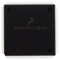
MC9S12HZ128VAL Freescale Semiconductor, MC9S12HZ128VAL Datasheet - Page 286

MC9S12HZ128VAL
Manufacturer Part Number
MC9S12HZ128VAL
Description
IC MCU 16BIT 2K FLASH 112-LQFP
Manufacturer
Freescale Semiconductor
Series
HCS12r
Datasheet
1.MC9S12HZ128CAL.pdf
(692 pages)
Specifications of MC9S12HZ128VAL
Core Processor
HCS12
Core Size
16-Bit
Speed
25MHz
Connectivity
CAN, EBI/EMI, I²C, SCI, SPI
Peripherals
LCD, Motor control PWM, POR, PWM, WDT
Number Of I /o
85
Program Memory Size
128KB (128K x 8)
Program Memory Type
FLASH
Eeprom Size
2K x 8
Ram Size
6K x 8
Voltage - Supply (vcc/vdd)
2.35 V ~ 5.5 V
Data Converters
A/D 16x10b
Oscillator Type
Internal
Operating Temperature
-40°C ~ 105°C
Package / Case
112-LQFP
Processor Series
S12H
Core
HCS12
Data Bus Width
16 bit
Data Ram Size
6 KB
Interface Type
I2C/SCI/SPI
Maximum Clock Frequency
50 MHz
Number Of Programmable I/os
85
Number Of Timers
8
Maximum Operating Temperature
+ 105 C
Mounting Style
SMD/SMT
3rd Party Development Tools
EWHCS12
Minimum Operating Temperature
- 40 C
On-chip Adc
16-ch x 10-bit
Lead Free Status / RoHS Status
Lead free / RoHS Compliant
Available stocks
Company
Part Number
Manufacturer
Quantity
Price
Company:
Part Number:
MC9S12HZ128VAL
Manufacturer:
Freescale Semiconductor
Quantity:
10 000
Part Number:
MC9S12HZ128VAL
Manufacturer:
FREESCALE
Quantity:
20 000
- Current page: 286 of 692
- Download datasheet (4Mb)
Chapter 9 Motor Controller (MC10B8CV1)
9.7
This section provides an example of how the PWM motor controller can be initialized and used by
application software. The configuration parameters (e.g., timer settings, duty cycle values, etc.) are not
guaranteed to be adequate for any real application.
The example software is implemented in assembly language.
9.7.1
One way to use the motor controller is:
The timer is disabled and the duty cycle registers are cleared to drive an inactive value on the PWM output
as long as the motor controller is enabled. The period register is cleared after a certain time, which disables
the motor controller. The table address is restored and the timer interrupt flag is cleared.
286
1. Perform global initialization
2. Perform the startup phase
3. Main program
4. Sub program
a) Set the motor controller control registers MCCTL0 and MCCTL1 to appropriate values.
b) Configure the channel control registers for the desired mode.
a) Clear the duty cycle registers MCDC0 and MCDC1
b) Initialize the period register MCPER, which is equivalent to enabling the motor controller.
c) Enable the timer which generates the timebase for the updates of the duty cycle registers.
a) Check if pin PB0 is set to “1” and execute the sub program if a timer interrupt is pending.
b) Initiate the shutdown procedure if pin PB0 is set to “0”.
a) Update the duty cycle registers
b) Shutdown procedure
Initialization/Application Information
i) Prescaler disabled (MCPRE1 = 0, MCPRE0 = 0).
ii) Fast mode and dither disabled (FAST = 0, DITH = 0).
iii) Recirculation feature in dual full H-bridge mode disabled (RECIRC = 0).
All other bits in MCCTL0 and MCCTL1 are set to 0.
i) Dual full H-bridge mode (MCOM[1:0] = 11).
ii) Left aligned PWM (MCAM[1:0] = 01).
iii) No channel delay (MCCD[1:0] = 00).
Load the duty cycle registers MCDC0 and MCDC1 with new values from the table and clear
the timer interrupt flag.
The sub program will initiate the shutdown procedure if pin PB0 is set to “0”.
Code Example
MC9S12HZ256 Data Sheet, Rev. 2.05
Freescale Semiconductor
Related parts for MC9S12HZ128VAL
Image
Part Number
Description
Manufacturer
Datasheet
Request
R
Part Number:
Description:
Manufacturer:
Freescale Semiconductor, Inc
Datasheet:
Part Number:
Description:
Manufacturer:
Freescale Semiconductor, Inc
Datasheet:
Part Number:
Description:
Manufacturer:
Freescale Semiconductor, Inc
Datasheet:
Part Number:
Description:
Manufacturer:
Freescale Semiconductor, Inc
Datasheet:
Part Number:
Description:
Manufacturer:
Freescale Semiconductor, Inc
Datasheet:
Part Number:
Description:
Manufacturer:
Freescale Semiconductor, Inc
Datasheet:
Part Number:
Description:
Manufacturer:
Freescale Semiconductor, Inc
Datasheet:
Part Number:
Description:
Manufacturer:
Freescale Semiconductor, Inc
Datasheet:
Part Number:
Description:
Manufacturer:
Freescale Semiconductor, Inc
Datasheet:
Part Number:
Description:
Manufacturer:
Freescale Semiconductor, Inc
Datasheet:
Part Number:
Description:
Manufacturer:
Freescale Semiconductor, Inc
Datasheet:
Part Number:
Description:
Manufacturer:
Freescale Semiconductor, Inc
Datasheet:
Part Number:
Description:
Manufacturer:
Freescale Semiconductor, Inc
Datasheet:
Part Number:
Description:
Manufacturer:
Freescale Semiconductor, Inc
Datasheet:
Part Number:
Description:
Manufacturer:
Freescale Semiconductor, Inc
Datasheet:


