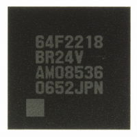
DF2218BR24V Renesas Electronics America, DF2218BR24V Datasheet - Page 46

DF2218BR24V
Manufacturer Part Number
DF2218BR24V
Description
IC H8S/2218 MCU FLASH 112-LFBGA
Manufacturer
Renesas Electronics America
Series
H8® H8S/2200r
Specifications of DF2218BR24V
Core Processor
H8S/2000
Core Size
16-Bit
Speed
24MHz
Connectivity
SCI, SmartCard, USB
Peripherals
DMA, POR, PWM, WDT
Number Of I /o
69
Program Memory Size
128KB (128K x 8)
Program Memory Type
FLASH
Ram Size
12K x 8
Voltage - Supply (vcc/vdd)
2.7 V ~ 3.6 V
Data Converters
A/D 6x10b
Oscillator Type
External
Operating Temperature
-20°C ~ 75°C
Package / Case
112-LFBGA
For Use With
HS0005KCU11H - EMULATOR E10A-USB H8S(X),SH2(A)3DK2218-SS - KIT DEV H8S/2218 WINDOWS SIDESHW3DK2218 - DEV EVAL KIT H8S/2218
Lead Free Status / RoHS Status
Lead free / RoHS Compliant
Eeprom Size
-
Available stocks
Company
Part Number
Manufacturer
Quantity
Price
Company:
Part Number:
DF2218BR24V
Manufacturer:
Renesas Electronics America
Quantity:
10 000
- Current page: 46 of 758
- Download datasheet (5Mb)
Figure 14.18 EP1 Bulk-In Transfer Operation............................................................................. 514
Figure 14.19 EP2 Bulk-Out Transfer Operation .......................................................................... 515
Figure 14.20 Forcible Stall by Firmware ..................................................................................... 518
Figure 14.21 Automatic Stall by USB Function Module ............................................................. 519
Figure 14.22 EP1PKTE Operation in UTRG0............................................................................. 521
Figure 14.23 EP2RDFN Operation in UTRG0 ............................................................................ 522
Figure 14.24 EP1PKTE Operation in UTRG0 (Auto-Request) ................................................... 523
Figure 14.25 EP2RDFN Operation in UTRG0 (Auto-Request) .................................................. 524
Figure 14.26 USB External Circuit in Bus-Powered Mode ......................................................... 525
Figure 14.27 USB External Circuit in Self-Powered Mode ......................................................... 526
Figure 14.28 Flowchart ................................................................................................................ 531
Figure 14.29 Timing Chart........................................................................................................... 532
Figure 14.30 TR Interrupt Flag Set Timing ................................................................................. 533
Section 15 A/D Converter
Figure 15.1 Block Diagram of A/D Converter........................................................................... 536
Figure 15.2 Access to ADDR (When Reading H'AA40) ........................................................... 541
Figure 15.3 A/D Conversion Timing (Single-Chip Mode, Channel 1 Selected)........................ 542
Figure 15.4 A/D Conversion Timing (Scan Mode, Channels AN0 to AN2 Selected) ............... 543
Figure 15.5 A/D Conversion Timing ......................................................................................... 544
Figure 15.6 External Trigger Input Timing................................................................................ 545
Figure 15.7 A/D Conversion Precision Definitions (1).............................................................. 547
Figure 15.8 A/D Conversion Precision Definitions (2).............................................................. 547
Figure 15.9 Example of Analog Input Circuit............................................................................ 548
Figure 15.10 Analog Input Pin Equivalent Circuit....................................................................... 549
Section 17 Flash Memory (F-ZTAT Version)
Figure 17.1 Block Diagram of Flash Memory ........................................................................... 554
Figure 17.2 Flash Memory State Transitions ............................................................................. 555
Figure 17.3 Boot Mode (Sample)............................................................................................... 556
Figure 17.4 User Program Mode (Sample) ................................................................................ 557
Figure 17.5 Flash Memory Block Configuration (HD64F2218, HD64F2218U,
Figure 17.6 Flash Memory Block Configuration
Figure 17.7 Flash Memory Block Configuration (HD64F2210CU) .......................................... 560
Figure 17.8 System Configuration in SCI Boot Mode ............................................................... 568
Figure 17.9 System Configuration Diagram when Using USB Boot Mode............................... 572
Figure 17.10 Programming/Erasing Flowchart Example in User Program Mode ....................... 576
Figure 17.11 Flowchart for Flash Memory Emulation in RAM................................................... 577
Figure 17.12 Example of RAM Overlap Operation ..................................................................... 578
Rev.7.00 Dec. 24, 2008 Page xliv of liv
REJ09B0074-0700
HD64F2218CU, HD64F2212, HD64F2212U, HD64F2212CU)............................ 558
(HD64F2217CU, HD64F2211, HD64F2211U, HD64F2211CU) .......................... 559
Related parts for DF2218BR24V
Image
Part Number
Description
Manufacturer
Datasheet
Request
R

Part Number:
Description:
CONN SOCKET 2POS 7.92MM WHITE
Manufacturer:
Hirose Electric Co Ltd
Datasheet:

Part Number:
Description:
CONN SOCKET 4POS 7.92MM WHITE
Manufacturer:
Hirose Electric Co Ltd
Datasheet:

Part Number:
Description:
CONN SOCKET 5POS 7.92MM WHITE
Manufacturer:
Hirose Electric Co Ltd
Datasheet:

Part Number:
Description:
CONN SOCKET 3POS 7.92MM WHITE
Manufacturer:
Hirose Electric Co Ltd
Datasheet:

Part Number:
Description:
CONN SOCKET 5POS 7.92MM WHITE
Manufacturer:
Hirose Electric Co Ltd
Datasheet:

Part Number:
Description:
CONN SOCKET 2POS 7.92MM WHITE
Manufacturer:
Hirose Electric Co Ltd
Datasheet:

Part Number:
Description:
CONN SOCKET 3POS 7.92MM WHITE
Manufacturer:
Hirose Electric Co Ltd
Datasheet:

Part Number:
Description:
CONN SOCKET 4POS 7.92MM WHITE
Manufacturer:
Hirose Electric Co Ltd
Datasheet:

Part Number:
Description:
CONN HEADER 2POS 7.92MM R/A TIN
Manufacturer:
Hirose Electric Co Ltd
Datasheet:

Part Number:
Description:
CONN HEADER 4POS 7.92MM R/A TIN
Manufacturer:
Hirose Electric Co Ltd
Datasheet:

Part Number:
Description:
KIT STARTER FOR M16C/29
Manufacturer:
Renesas Electronics America
Datasheet:

Part Number:
Description:
KIT STARTER FOR R8C/2D
Manufacturer:
Renesas Electronics America
Datasheet:

Part Number:
Description:
R0K33062P STARTER KIT
Manufacturer:
Renesas Electronics America
Datasheet:

Part Number:
Description:
KIT STARTER FOR R8C/23 E8A
Manufacturer:
Renesas Electronics America
Datasheet:

Part Number:
Description:
KIT STARTER FOR R8C/25
Manufacturer:
Renesas Electronics America
Datasheet:


