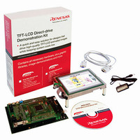
YLCDRSK2378 Renesas Electronics America, YLCDRSK2378 Datasheet - Page 64

YLCDRSK2378
Manufacturer Part Number
YLCDRSK2378
Description
KIT DEV EVAL H8S/2378 LCD
Manufacturer
Renesas Electronics America
Series
H8®r
Datasheet
1.YR0K42378FC000BA.pdf
(1208 pages)
Specifications of YLCDRSK2378
Main Purpose
Displays, LCD Controller
Embedded
Yes, MCU, 16-Bit
Utilized Ic / Part
YLCDRSK2378
Primary Attributes
5.7" QVGA, Touch Screen
Secondary Attributes
Source Code on CD, Debugging Requires Emulator Cable E10A USB/JTAG
Lead Free Status / RoHS Status
Lead free / RoHS Compliant
- Current page: 64 of 1208
- Download datasheet (8Mb)
Table 11.29 Cascaded Combinations .......................................................................................... 596
Table 11.30 PWM Output Registers and Output Pins................................................................. 599
Table 11.31 Clock Input Pins in Phase Counting Mode.............................................................. 603
Table 11.32 Up/Down-Count Conditions in Phase Counting Mode 1 ........................................ 604
Table 11.33 Up/Down-Count Conditions in Phase Counting Mode 2 ........................................ 605
Table 11.34 Up/Down-Count Conditions in Phase Counting Mode 3 ........................................ 606
Table 11.35 Up/Down-Count Conditions in Phase Counting Mode 4 ........................................ 607
Table 11.36 TPU Interrupts......................................................................................................... 610
Section 12 Programmable Pulse Generator (PPG) ............................................ 631
Table 12.1
Section 13 8-Bit Timers (TMR) ........................................................................ 653
Table 13.1
Table 13.2
Table 13.3
Table 13.4
Table 13.5
Section 14 Watchdog Timer (WDT) ................................................................. 677
Table 14.1
Table 14.2
Section 15 Serial Communication Interface (SCI, IrDA).................................. 689
Table 15.1
Table 15.2
Table 15.3
Table 15.4
Table 15.5
Table 15.6
Table 15.7
Table 15.8
Table 15.9
Table 15.10 Serial Transfer Formats (Asynchronous Mode) ...................................................... 724
Table 15.11 SSR Status Flags and Receive Data Handling......................................................... 731
Table 15.12 Settings of Bits IrCKS2 to IrCKS0 ......................................................................... 761
Table 15.13 SCI Interrupt Sources .............................................................................................. 763
Table 15.14 Interrupt Sources ..................................................................................................... 764
Rev.7.00 Mar. 18, 2009 page lxii of lxvi
REJ09B0109-0700
Pin Configuration .................................................................................................... 633
Pin Configuration .................................................................................................... 655
Clock Input to TCNT and Count Condition ............................................................ 658
8-Bit Timer Interrupt Sources ................................................................................. 669
Timer Output Priorities ........................................................................................... 673
Switching of Internal Clock and TCNT Operation.................................................. 674
Pin Configuration .................................................................................................... 678
WDT Interrupt Source............................................................................................. 684
Pin Configuration .................................................................................................... 692
Relationships between N Setting in BRR and Bit Rate B ....................................... 711
BRR Settings for Various Bit Rates (Asynchronous Mode) ................................... 712
Maximum Bit Rate for Each Frequency (Asynchronous Mode) ............................. 715
Maximum Bit Rate with External Clock Input (Asynchronous Mode)................... 716
BRR Settings for Various Bit Rates (Clocked Synchronous Mode) ....................... 717
Maximum Bit Rate with External Clock Input (Clocked Synchronous Mode)....... 718
Examples of Bit Rate for Various BRR Settings (Smart Card Interface Mode)
(when n = 0 and S = 372) ........................................................................................ 718
Maximum Bit Rate at Various Frequencies (Smart Card Interface Mode)
(when S = 372) ........................................................................................................ 719
Related parts for YLCDRSK2378
Image
Part Number
Description
Manufacturer
Datasheet
Request
R

Part Number:
Description:
KIT STARTER FOR M16C/29
Manufacturer:
Renesas Electronics America
Datasheet:

Part Number:
Description:
KIT STARTER FOR R8C/2D
Manufacturer:
Renesas Electronics America
Datasheet:

Part Number:
Description:
R0K33062P STARTER KIT
Manufacturer:
Renesas Electronics America
Datasheet:

Part Number:
Description:
KIT STARTER FOR R8C/23 E8A
Manufacturer:
Renesas Electronics America
Datasheet:

Part Number:
Description:
KIT STARTER FOR R8C/25
Manufacturer:
Renesas Electronics America
Datasheet:

Part Number:
Description:
KIT STARTER H8S2456 SHARPE DSPLY
Manufacturer:
Renesas Electronics America
Datasheet:

Part Number:
Description:
KIT STARTER FOR R8C38C
Manufacturer:
Renesas Electronics America
Datasheet:

Part Number:
Description:
KIT STARTER FOR R8C35C
Manufacturer:
Renesas Electronics America
Datasheet:

Part Number:
Description:
KIT STARTER FOR R8CL3AC+LCD APPS
Manufacturer:
Renesas Electronics America
Datasheet:

Part Number:
Description:
KIT STARTER FOR RX610
Manufacturer:
Renesas Electronics America
Datasheet:

Part Number:
Description:
KIT STARTER FOR R32C/118
Manufacturer:
Renesas Electronics America
Datasheet:

Part Number:
Description:
KIT DEV RSK-R8C/26-29
Manufacturer:
Renesas Electronics America
Datasheet:

Part Number:
Description:
KIT STARTER FOR SH7124
Manufacturer:
Renesas Electronics America
Datasheet:

Part Number:
Description:
KIT STARTER FOR H8SX/1622
Manufacturer:
Renesas Electronics America
Datasheet:

Part Number:
Description:
KIT DEV FOR SH7203
Manufacturer:
Renesas Electronics America
Datasheet:


