YLCDRSK2378 Renesas Electronics America, YLCDRSK2378 Datasheet - Page 969
YLCDRSK2378
Manufacturer Part Number
YLCDRSK2378
Description
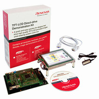
KIT DEV EVAL H8S/2378 LCD
Manufacturer
Renesas Electronics America
Series
H8®r
Datasheet
1.YR0K42378FC000BA.pdf
(1208 pages)
Specifications of YLCDRSK2378
Main Purpose
Displays, LCD Controller
Embedded
Yes, MCU, 16-Bit
Utilized Ic / Part
YLCDRSK2378
Primary Attributes
5.7" QVGA, Touch Screen
Secondary Attributes
Source Code on CD, Debugging Requires Emulator Cable E10A USB/JTAG
Lead Free Status / RoHS Status
Lead free / RoHS Compliant


8. The return value in the initialization program, FPFR (general register R0L) is determined.
9. All interrupts and the use of a bus master other than the CPU are prohibited.
10. FKEY must be set to H'5A and the user MAT must be prepared for programming.
11. The parameter which is required for programming is set.
⎯ Interrupts can be accepted during the execution of the initialization program. The program
The specified voltage is applied for the specified time when programming or erasing. If
interrupts occur or the bus mastership is moved to other than the CPU during this time, the
voltage for more than the specified time will be applied and flash memory may be damaged.
Therefore, interrupts, movement of bus mastership to other than the CPU (DMAC, DTC, or
BREQ), and transition to DRAM refresh cycles are prohibited.
To prohibit the interrupt, bit 7 (I) in the condition code register (CCR) of the CPU should be
set to B'1 in interrupt control mode 0 or bits 2 to 0 (I2 to I0) in the extend control register of
the CPU should be set to B'111 in interrupt control mode 2. Then interrupts other than NMI are
held and are not executed.
The NMI interrupts must be masked within the user system.
The interrupts that are held must be executed after all program processing.
When the bus mastership is moved to other than the CPU by the DMAC, DTC, or BREQ
signal or DRAM refresh cycles are entered, the error protection state is entered. Therefore,
taking bus mastership by the DMAC, DTC, or BREQ signal is prohibited.
The start address of the programming destination of the user MAT (FMPAR) is set to general
register ER1. The start address of the program data area (FMPDR) is set to general register
ER0.
⎯ Example of the FMPAR setting
⎯ Example of the FMPDR setting
storage area and stack area in the on-chip RAM and register values must not be destroyed.
FMPAR specifies the programming destination address. When an address other than one in
the user MAT area is specified, even if the programming program is executed,
programming is not executed and an error is returned to the return value parameter FPFR.
Since the unit is 128 bytes, the lower eight bits (A7 to A0) must be H'00 or H'80 as the
boundary of 128 bytes.
When the storage destination of the program data is flash memory, even if the program
execution routine is executed, programming is not executed and an error is returned to the
FPFR parameter. In this case, the program data must be transferred to the on-chip RAM
and then programming must be executed.
Section 21 Flash Memory (0.18-μm F-ZTAT Version)
Rev.7.00 Mar. 18, 2009 page 901 of 1136
REJ09B0109-0700
Related parts for YLCDRSK2378
Image
Part Number
Description
Manufacturer
Datasheet
Request
R

Part Number:
Description:
KIT STARTER FOR M16C/29
Manufacturer:
Renesas Electronics America
Datasheet:

Part Number:
Description:
KIT STARTER FOR R8C/2D
Manufacturer:
Renesas Electronics America
Datasheet:

Part Number:
Description:
R0K33062P STARTER KIT
Manufacturer:
Renesas Electronics America
Datasheet:

Part Number:
Description:
KIT STARTER FOR R8C/23 E8A
Manufacturer:
Renesas Electronics America
Datasheet:

Part Number:
Description:
KIT STARTER FOR R8C/25
Manufacturer:
Renesas Electronics America
Datasheet:

Part Number:
Description:
KIT STARTER H8S2456 SHARPE DSPLY
Manufacturer:
Renesas Electronics America
Datasheet:

Part Number:
Description:
KIT STARTER FOR R8C38C
Manufacturer:
Renesas Electronics America
Datasheet:

Part Number:
Description:
KIT STARTER FOR R8C35C
Manufacturer:
Renesas Electronics America
Datasheet:

Part Number:
Description:
KIT STARTER FOR R8CL3AC+LCD APPS
Manufacturer:
Renesas Electronics America
Datasheet:
Part Number:
Description:
KIT STARTER FOR RX610
Manufacturer:
Renesas Electronics America
Datasheet:

Part Number:
Description:
KIT STARTER FOR R32C/118
Manufacturer:
Renesas Electronics America
Datasheet:

Part Number:
Description:
KIT DEV RSK-R8C/26-29
Manufacturer:
Renesas Electronics America
Datasheet:

Part Number:
Description:
KIT STARTER FOR SH7124
Manufacturer:
Renesas Electronics America
Datasheet:

Part Number:
Description:
KIT STARTER FOR H8SX/1622
Manufacturer:
Renesas Electronics America
Datasheet:

Part Number:
Description:
KIT DEV FOR SH7203
Manufacturer:
Renesas Electronics America
Datasheet: