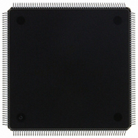
MCF5307AI90B Freescale Semiconductor, MCF5307AI90B Datasheet - Page 139

MCF5307AI90B
Manufacturer Part Number
MCF5307AI90B
Description
IC MPU 32BIT COLDF 90MHZ 208FQFP
Manufacturer
Freescale Semiconductor
Series
MCF530xr
Datasheets
1.MCF5307AI66B.pdf
(484 pages)
2.MCF5307AI66B.pdf
(16 pages)
3.MCF5307AI66B.pdf
(2 pages)
Specifications of MCF5307AI90B
Core Processor
Coldfire V3
Core Size
32-Bit
Speed
90MHz
Connectivity
EBI/EMI, I²C, UART/USART
Peripherals
DMA, POR, WDT
Number Of I /o
16
Program Memory Type
ROMless
Ram Size
4K x 8
Voltage - Supply (vcc/vdd)
3 V ~ 3.6 V
Oscillator Type
External
Operating Temperature
0°C ~ 70°C
Package / Case
208-FQFP
Maximum Clock Frequency
90 MHz
Maximum Operating Temperature
+ 105 C
Mounting Style
SMD/SMT
Minimum Operating Temperature
0 C
Family Name
MCF5xxx
Device Core
ColdFire
Device Core Size
32b
Frequency (max)
90MHz
Instruction Set Architecture
RISC
Supply Voltage 1 (typ)
3.3V
Operating Temp Range
0C to 70C
Operating Temperature Classification
Commercial
Mounting
Surface Mount
Pin Count
208
Package Type
FQFP
Program Memory Size
8KB
Cpu Speed
90MHz
Embedded Interface Type
I2C, UART
Digital Ic Case Style
FQFP
No. Of Pins
208
Supply Voltage Range
3V To 3.6V
Rohs Compliant
Yes
Lead Free Status / RoHS Status
Lead free / RoHS Compliant
Eeprom Size
-
Program Memory Size
-
Data Converters
-
Lead Free Status / Rohs Status
Lead free / RoHS Compliant
Available stocks
Company
Part Number
Manufacturer
Quantity
Price
Company:
Part Number:
MCF5307AI90B
Manufacturer:
FREESCAL
Quantity:
153
Company:
Part Number:
MCF5307AI90B
Manufacturer:
Freescale Semiconductor
Quantity:
10 000
Part Number:
MCF5307AI90B
Manufacturer:
FREESCALE
Quantity:
20 000
- Current page: 139 of 484
- Download datasheet (6Mb)
31–28
23–20
12–11
Bit
27
26
25
24
19
18
17
16
15
14
13
BSTAT Breakpoint status. Provides read-only status information concerning hardware breakpoints. BSTAT
FOF
TRG
HALT
BKPT
HRL
—
BKD
PCD
IPW
MAP
TRC
EMU
DDC
Name
is cleared by a TDR write or by a CSR read when either a level-2 breakpoint is triggered or a
level-1 breakpoint is triggered and the level-2 breakpoint is disabled.
0000 No breakpoints enabled
0001 Waiting for level-1 breakpoint
0010 Level-1 breakpoint triggered
0101 Waiting for level-2 breakpoint
0110 Level-2 breakpoint triggered
Fault-on-fault. If FOF is set, a catastrophic halt occurred and forced entry into BDM.
Hardware breakpoint trigger. If TRG is set, a hardware breakpoint halted the processor core and
forced entry into BDM. Reset and the debug
Processor halt. If HALT is set, the processor executed a HALT and forced entry into BDM. Reset
and the debug
Breakpoint assert. If BKPT is set, BKPT was asserted, forcing the processor into BDM. Reset and
the debug
Hardware revision level. Indicates the level of debug module functionality. An emulator could use
this information to identify the level of functionality supported.
0000 Initial debug functionality (Revision A)
0001 Revision B (this is the only valid value for the MCF5307)
Reserved, should be cleared.
Breakpoint disable. Used to disable the normal BKPT input functionality and to allow the assertion
of BKPT to generate a debug interrupt.
0 Normal operation
1 BKPT is edge-sensitive: a high-to-low edge on BKPT signals a debug interrupt to the processor.
PSTCLK disable. Setting PCD disables generation of PSTCLK, PST and DDATA outputs and
forces them to remain quiescent.
Inhibit processor writes. Setting IPW inhibits processor-initiated writes to the debug module’s
programming model registers. IPW can be modified only by commands from the external
development system.
Force processor references in emulator mode.
0 All emulator-mode references are mapped into supervisor code and data spaces.
1 The processor maps all references while in emulator mode to a special address space, TT = 10,
Force emulation mode on trace exception. If TRC = 1, the processor enters emulator mode when a
trace exception occurs.
Force emulation mode. If EMU = 1, the processor begins executing in emulator mode. See
Section 5.6.1.1, “Emulator Mode.”
Debug data control. Controls operand data capture for DDATA, which displays the number of bytes
defined by the operand reference size before the actual data; byte displays 8 bits, word displays 16
bits, and long displays 32 bits (one nibble at a time across multiple clock cycles). See Table 5-2.
00 No operand data is displayed.
01 Capture all write data.
10 Capture all read data.
11 Capture all read and write data.
The processor makes this interrupt request pending until the next sample point, when the
exception is initiated. In the ColdFire architecture, the interrupt sample point occurs once per
instruction. There is no support for nesting debug interrupts.
TM = 101 or 110.
GO
Freescale Semiconductor, Inc.
command clears this bit.
For More Information On This Product,
GO
Table 5-8. CSR Field Descriptions
command reset HALT.
Chapter 5. Debug Support
Go to: www.freescale.com
Description
GO
command clear TRG.
Programming Model
5-11
Related parts for MCF5307AI90B
Image
Part Number
Description
Manufacturer
Datasheet
Request
R
Part Number:
Description:
Manufacturer:
Freescale Semiconductor, Inc
Datasheet:
Part Number:
Description:
Mcf5307 Coldfire Integrated Microprocessor User
Manufacturer:
Freescale Semiconductor, Inc
Datasheet:
Part Number:
Description:
Manufacturer:
Freescale Semiconductor, Inc
Datasheet:
Part Number:
Description:
Manufacturer:
Freescale Semiconductor, Inc
Datasheet:
Part Number:
Description:
Manufacturer:
Freescale Semiconductor, Inc
Datasheet:
Part Number:
Description:
Manufacturer:
Freescale Semiconductor, Inc
Datasheet:
Part Number:
Description:
Manufacturer:
Freescale Semiconductor, Inc
Datasheet:
Part Number:
Description:
Manufacturer:
Freescale Semiconductor, Inc
Datasheet:
Part Number:
Description:
Manufacturer:
Freescale Semiconductor, Inc
Datasheet:
Part Number:
Description:
Manufacturer:
Freescale Semiconductor, Inc
Datasheet:
Part Number:
Description:
Manufacturer:
Freescale Semiconductor, Inc
Datasheet:
Part Number:
Description:
Manufacturer:
Freescale Semiconductor, Inc
Datasheet:
Part Number:
Description:
Manufacturer:
Freescale Semiconductor, Inc
Datasheet:
Part Number:
Description:
Manufacturer:
Freescale Semiconductor, Inc
Datasheet:
Part Number:
Description:
Manufacturer:
Freescale Semiconductor, Inc
Datasheet:


