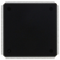
MCF5307AI90B Freescale Semiconductor, MCF5307AI90B Datasheet - Page 334

MCF5307AI90B
Manufacturer Part Number
MCF5307AI90B
Description
IC MPU 32BIT COLDF 90MHZ 208FQFP
Manufacturer
Freescale Semiconductor
Series
MCF530xr
Datasheets
1.MCF5307AI66B.pdf
(484 pages)
2.MCF5307AI66B.pdf
(16 pages)
3.MCF5307AI66B.pdf
(2 pages)
Specifications of MCF5307AI90B
Core Processor
Coldfire V3
Core Size
32-Bit
Speed
90MHz
Connectivity
EBI/EMI, I²C, UART/USART
Peripherals
DMA, POR, WDT
Number Of I /o
16
Program Memory Type
ROMless
Ram Size
4K x 8
Voltage - Supply (vcc/vdd)
3 V ~ 3.6 V
Oscillator Type
External
Operating Temperature
0°C ~ 70°C
Package / Case
208-FQFP
Maximum Clock Frequency
90 MHz
Maximum Operating Temperature
+ 105 C
Mounting Style
SMD/SMT
Minimum Operating Temperature
0 C
Family Name
MCF5xxx
Device Core
ColdFire
Device Core Size
32b
Frequency (max)
90MHz
Instruction Set Architecture
RISC
Supply Voltage 1 (typ)
3.3V
Operating Temp Range
0C to 70C
Operating Temperature Classification
Commercial
Mounting
Surface Mount
Pin Count
208
Package Type
FQFP
Program Memory Size
8KB
Cpu Speed
90MHz
Embedded Interface Type
I2C, UART
Digital Ic Case Style
FQFP
No. Of Pins
208
Supply Voltage Range
3V To 3.6V
Rohs Compliant
Yes
Lead Free Status / RoHS Status
Lead free / RoHS Compliant
Eeprom Size
-
Program Memory Size
-
Data Converters
-
Lead Free Status / Rohs Status
Lead free / RoHS Compliant
Available stocks
Company
Part Number
Manufacturer
Quantity
Price
Company:
Part Number:
MCF5307AI90B
Manufacturer:
FREESCAL
Quantity:
153
Company:
Part Number:
MCF5307AI90B
Manufacturer:
Freescale Semiconductor
Quantity:
10 000
Part Number:
MCF5307AI90B
Manufacturer:
FREESCALE
Quantity:
20 000
- Current page: 334 of 484
- Download datasheet (6Mb)
Operation
The receiver detects the beginning of a break in the middle of a character if the break
persists through the next character time. If the break begins in the middle of a character, the
receiver places the damaged character in the Rx FIFO stack and sets the corresponding
USRn error bits and USRn[RxRDY]. Then, if the break lasts until the next character time,
the receiver places an all-zero character into the Rx FIFO and sets USRn[RB,RxRDY].
14.5.2.3 FIFO Stack
The FIFO stack is used in the UART’s receiver buffer logic. The stack consists of three
receiver holding registers. The receive buffer consists of the FIFO and a receiver shift
register connected to the RxD (see Figure 14-20). Data is assembled in the receiver shift
register and loaded into the top empty receiver holding register position of the FIFO. Thus,
data flowing from the receiver to the CPU is quadruple-buffered.
In addition to the data byte, three status bits, parity error (PE), framing error (FE), and
received break (RB), are appended to each data character in the FIFO; OE (overrun error)
is not appended. By programming the ERR bit in the channel’s mode register (UMR1n),
status is provided in character or block modes.
USRn[RxRDY] is set when at least one character is available to be read by the CPU. A read
of the receiver buffer produces an output of data from the top of the FIFO stack. After the
read cycle, the data at the top of the FIFO stack and its associated status bits are popped and
the receiver shift register can add new data at the bottom of the stack. The FIFO-full status
bit (FFULL) is set if all three stack positions are filled with data. Either the RxRDY or
FFULL bit can be selected to cause an interrupt.
The two error modes are selected by UMR1n[ERR] as follows:
In either mode, reading the USRn does not affect the FIFO. The FIFO is popped only when
the receive buffer is read. The USRn should be read before reading the receive buffer. If all
three receiver holding registers are full, a new character is held in the receiver shift register
until space is available. However, if a second new character is received, the contents of the
the character in the receiver shift register is lost, the FIFOs are unaffected, and USRn[OE]
is set when the receiver detects the start bit of the new overrunning character.
To support flow control, the receiver can be programmed to automatically negate and assert
RTS, in which case the receiver automatically negates RTS when a valid start bit is detected
and the FIFO stack is full. The receiver asserts RTS when a FIFO position becomes
14-24
• In character mode (UMR1n[ERR] = 0, status is given in the USRn for the character
• In block mode, the USRn shows a logical OR of all characters reaching the top of
at the top of the FIFO.
the FIFO stack since the last
characters reach the top of the FIFO stack. Block mode offers a data-reception speed
advantage where the software overhead of error-checking each character cannot be
tolerated. However, errors are not detected until the check is performed at the end of
an entire message—the faulting character is not identified.
Freescale Semiconductor, Inc.
For More Information On This Product,
Go to: www.freescale.com
MCF5307 User’s Manual
RESET ERROR STATUS
command. Status is updated as
Related parts for MCF5307AI90B
Image
Part Number
Description
Manufacturer
Datasheet
Request
R
Part Number:
Description:
Manufacturer:
Freescale Semiconductor, Inc
Datasheet:
Part Number:
Description:
Mcf5307 Coldfire Integrated Microprocessor User
Manufacturer:
Freescale Semiconductor, Inc
Datasheet:
Part Number:
Description:
Manufacturer:
Freescale Semiconductor, Inc
Datasheet:
Part Number:
Description:
Manufacturer:
Freescale Semiconductor, Inc
Datasheet:
Part Number:
Description:
Manufacturer:
Freescale Semiconductor, Inc
Datasheet:
Part Number:
Description:
Manufacturer:
Freescale Semiconductor, Inc
Datasheet:
Part Number:
Description:
Manufacturer:
Freescale Semiconductor, Inc
Datasheet:
Part Number:
Description:
Manufacturer:
Freescale Semiconductor, Inc
Datasheet:
Part Number:
Description:
Manufacturer:
Freescale Semiconductor, Inc
Datasheet:
Part Number:
Description:
Manufacturer:
Freescale Semiconductor, Inc
Datasheet:
Part Number:
Description:
Manufacturer:
Freescale Semiconductor, Inc
Datasheet:
Part Number:
Description:
Manufacturer:
Freescale Semiconductor, Inc
Datasheet:
Part Number:
Description:
Manufacturer:
Freescale Semiconductor, Inc
Datasheet:
Part Number:
Description:
Manufacturer:
Freescale Semiconductor, Inc
Datasheet:
Part Number:
Description:
Manufacturer:
Freescale Semiconductor, Inc
Datasheet:


