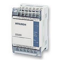
FX1S-30MR-ES/UL MITSUBISHI, FX1S-30MR-ES/UL Datasheet - Page 113

FX1S-30MR-ES/UL
Manufacturer Part Number
FX1S-30MR-ES/UL
Description
PLC, 16 IN, 14 RELAY OUT, 110V/2
Manufacturer
MITSUBISHI
Datasheet
1.FX1S-30MR-ESUL.pdf
(380 pages)
Specifications of FX1S-30MR-ES/UL
No. Of Analogue Inputs
16
No. Of Analogue Outputs
14
Ip/nema Rating
IP10
Approval Bodies
CE, CUL, UL
External Depth
49mm
External Length / Height
90mm
External Width
60mm
Mounting Type
Panel
- Current page: 113 of 380
- Download datasheet (7Mb)
4.14.2
4.14.3
FX Series Programmable Controllers
Word Devices
Word devices such as T, C, D, V and Z can store data about a particular event or action within
the PLC. For the most part these devices are 16 bit registers. However, certain variations do
have 32 bit capabilities, as can pairs of consecutive data registers or combined V and Z
registers.
It may seem strange to quote the size of a word device in bits. This is not so strange when it is
considered that the bit is the smallest unit of data within the PLC. So by identifying every thing
in bit format a common denomination is being used, hence comparison etc is much easier.
Additional consequences of this bit interpretation is that the actual data can be interpreted
differently. The physical pattern of the active bits may be the important feature or perhaps the
numerical interpretation of the bit pattern may be the key to the program. It all comes down to
how the information is read.
Interpreting Word Data
As word data can be read in many ways the significance of certain parts of the word data can
change. PLC’s can read the word data as:
The following examples will show how the same piece of data can become many different
things depending wholly on the way the information is read or interpreted.
- A pure bit pattern
- A decimal number
- A hexadecimal number
- Or as a BCD (Binary Coded Decimal) number
a) Considering a bit pattern
The following bit pattern means nothing - it is simply 16 devices which have two states.
Some of the devices are randomly set to one of the states. However, if the header
notation (base 2) is added to the 16 bit data the sum, decimal, total of the active bits can
be calculated, e.g.,
Decimal value =
Decimal value =
This is in fact incorrect!
There is one bit device which has been shaded in. If its header notation is studied
carefully it will be noted that it says MSB. This is the Most Significant Bit. This single bit
device will determine if the data will be interpreted as a positive or negative number. In
this example the MSB is equal to 1. This means the data is negative.
The answer however, is not -7797.
MSB
1 0 0 1 1 1 1 0 0 1 1 1 0 1 0 1
1 0 0 1 1 1 1 0 0 1 1 1 0 1 0 1
2 2 2 2 2 2 2 2 2 2 2 2 2 2 2
(2
+(2
7797
14
0
5
13
x 1) + (2
x 1) + (2
12
11
2
9
x 1) + (2
10
x 1) + (2
9
8
4
10
x 1) + (2
7
x 1) + (2
6
5
5
x 1)
4
x 1) + (2
3
2
1
12
x 1)
Devices in Detail 4
0
4-39
Related parts for FX1S-30MR-ES/UL
Image
Part Number
Description
Manufacturer
Datasheet
Request
R

Part Number:
Description:
MITSUBISHI IGBT MODULES
Manufacturer:
MITSUBISHI
Datasheet:

Part Number:
Description:
MITSUBISHI INTELLIGENT POWER MODULES
Manufacturer:
MITSUBISHI
Datasheet:

Part Number:
Description:
TRANSFER-MOLD TYPE INSULATED TYPE
Manufacturer:
MITSUBISHI
Datasheet:

Part Number:
Description:
Manufacturer:
MITSUBISHI
Datasheet:

Part Number:
Description:
30A intelligent power module for flat-base type
Manufacturer:
MITSUBISHI
Datasheet:

Part Number:
Description:
15A - transistor module for medium power switching use, insulated type
Manufacturer:
MITSUBISHI
Datasheet:

Part Number:
Description:
5A power module for transfer-mold type insulated type
Manufacturer:
MITSUBISHI
Datasheet:

Part Number:
Description:
30A intelligent power module for flat-base type
Manufacturer:
MITSUBISHI
Datasheet:

Part Number:
Description:
TRANSFER-MOLD TYPE INSULATED TYPE
Manufacturer:
MITSUBISHI
Datasheet:

Part Number:
Description:
TRANSFER-MOLD TYPE INSULATED TYPE
Manufacturer:
MITSUBISHI
Datasheet:

Part Number:
Description:
20A - transistor module for medium power switching use, insulated type
Manufacturer:
MITSUBISHI
Datasheet:

Part Number:
Description:
20A - transistor module for medium power switching use, insulated type
Manufacturer:
MITSUBISHI
Datasheet:


