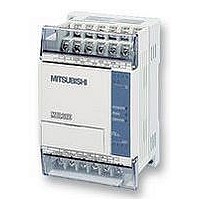
FX1S-30MR-ES/UL MITSUBISHI, FX1S-30MR-ES/UL Datasheet - Page 153

FX1S-30MR-ES/UL
Manufacturer Part Number
FX1S-30MR-ES/UL
Description
PLC, 16 IN, 14 RELAY OUT, 110V/2
Manufacturer
MITSUBISHI
Datasheet
1.FX1S-30MR-ESUL.pdf
(380 pages)
Specifications of FX1S-30MR-ES/UL
No. Of Analogue Inputs
16
No. Of Analogue Outputs
14
Ip/nema Rating
IP10
Approval Bodies
CE, CUL, UL
External Depth
49mm
External Length / Height
90mm
External Width
60mm
Mounting Type
Panel
- Current page: 153 of 380
- Download datasheet (7Mb)
5.3.9
5.3.10
FX Series Programmable Controlers
WXOR (FNC 28)
The following rules are used to determine the result of a logical XOR operation. This takes
place for every bit contained within the source devices:
General rule: (S
1 WXOR 1 = 0
1 WXOR 0 = 1
NEG (FNC 29)
When this is complete, a further binary 1 is added to the bit pattern. The result is the total
logical sign change of the selected devices contents, e.g. a positive number will become a
negative number or a negative number will become a positive.
WXOR
FNC 28
(Logical
exclusive
OR)
NEG
FNC 29
(Negation)
Mnemonic
Mnemonic
A logical XOR is
performed on the
source devices -
result stored at
destination
Logically inverts
the contents of
the designated
device
1
)Bit
Function
Function
n
0 WXOR 1 = 1
0 WXOR 0 = 0
WXOR (S
K, H
KnX, KnY, KnM, KnS,
T, C, D, V, Z
KnY, KnM, KnS,
T, C, D, V, Z
2
)Bit
n
S1
= (D)Bit
Operation :
The bit patterns of the two source devices are
analyzed (the contents of S
the contents of S
analysis is stored in the destination device (D).
Operation :
The bit pattern of the selected device is inverted.
This means any occurrence of a ‘1’ becomes a ‘0’
and any occurrence of a ‘0’ will be written as a ‘1’.
n
Operands
Operands
S2
D
KnY, KnM, KnS,
T, C, D, V, Z
1
). The result of the logical XOR
D
2
is compared against
Applied Instructions 5
WXOR,
WXORP:
7 steps
DXOR,DXORP
13 steps
NEG,NEGP:
3 steps
DNEG,
DNEGP:
5 steps
Program steps
Program steps
5-31
Related parts for FX1S-30MR-ES/UL
Image
Part Number
Description
Manufacturer
Datasheet
Request
R

Part Number:
Description:
MITSUBISHI IGBT MODULES
Manufacturer:
MITSUBISHI
Datasheet:

Part Number:
Description:
MITSUBISHI INTELLIGENT POWER MODULES
Manufacturer:
MITSUBISHI
Datasheet:

Part Number:
Description:
TRANSFER-MOLD TYPE INSULATED TYPE
Manufacturer:
MITSUBISHI
Datasheet:

Part Number:
Description:
Manufacturer:
MITSUBISHI
Datasheet:

Part Number:
Description:
30A intelligent power module for flat-base type
Manufacturer:
MITSUBISHI
Datasheet:

Part Number:
Description:
15A - transistor module for medium power switching use, insulated type
Manufacturer:
MITSUBISHI
Datasheet:

Part Number:
Description:
5A power module for transfer-mold type insulated type
Manufacturer:
MITSUBISHI
Datasheet:

Part Number:
Description:
30A intelligent power module for flat-base type
Manufacturer:
MITSUBISHI
Datasheet:

Part Number:
Description:
TRANSFER-MOLD TYPE INSULATED TYPE
Manufacturer:
MITSUBISHI
Datasheet:

Part Number:
Description:
TRANSFER-MOLD TYPE INSULATED TYPE
Manufacturer:
MITSUBISHI
Datasheet:

Part Number:
Description:
20A - transistor module for medium power switching use, insulated type
Manufacturer:
MITSUBISHI
Datasheet:

Part Number:
Description:
20A - transistor module for medium power switching use, insulated type
Manufacturer:
MITSUBISHI
Datasheet:


