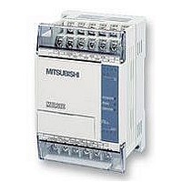
FX1S-30MR-ES/UL MITSUBISHI, FX1S-30MR-ES/UL Datasheet - Page 339

FX1S-30MR-ES/UL
Manufacturer Part Number
FX1S-30MR-ES/UL
Description
PLC, 16 IN, 14 RELAY OUT, 110V/2
Manufacturer
MITSUBISHI
Datasheet
1.FX1S-30MR-ESUL.pdf
(380 pages)
Specifications of FX1S-30MR-ES/UL
No. Of Analogue Inputs
16
No. Of Analogue Outputs
14
Ip/nema Rating
IP10
Approval Bodies
CE, CUL, UL
External Depth
49mm
External Length / Height
90mm
External Width
60mm
Mounting Type
Panel
- Current page: 339 of 380
- Download datasheet (7Mb)
10.9.2
10.10 Using The Execution Complete Flag, M8029
FX Series Programmable Controllers
A 0.1 msec timer pulse measurement
This is a very accurate measuring process for pulse
inputs. The use of a standard timer is not accurate
enough in this case as the highest resolution is
1msec. Therefor, this example shows how the
special high accuracy devices M8099 and D8099
are used to capture the 0.1 msec resolution pulse
data.
Explanation:
The incoming pulse is captured between two
i n t e r r u p t r o u t i n e s . T h e s e r o u t in e s o p e r a t e
independently of each other, one on the rising edge
of the pulse input and one on the falling edge of the
same input. During the pulse input the contents of
special register D8099 are continually moved into
data register D0. Once the pulse has completed the
contents of D0 can be viewed at leisure.
Please note for this high speed/accuracy mode to
be active for D8099, the corresponding special
auxiliary bit device M8099 must be driven ON in the
main program.
Some of the applied instructions take more than one program scan to complete their operation.
This makes identification of the current operating state difficult. As an aid to the programmer,
certainappliedinstructionsidentify theircompletionbysettinganoperationcompleteflag, M8029.
Because this flag can be used by several different instructions at the same time, a method
similar to the following should be used to trap the M8029 status at each of the instructions
using it:
Explanation:
The M8029 'trapping’ sequence takes advantage of
the batch refresh of the FX family of PLC’s. As the
program scan passes each instruction using M8029
the status of M8029 changes to reflect the current
status of the instruction. Hence, by immediately
resetting (or setting) the drive flag for the instruction
the current operational status of the instruction is
trapped. So when the batch refresh takes place
only the completed instructions are reset. The
example above uses a pulse to set the drive flags
so that it is easy to monitor and see when each
in s t ru c t io n f i n i s h e s ( i f t h e in s t ru c t io n s a r e
continuously driven it will be difficult to see when
they finish!).
Points Of Technique 10
10-7
Related parts for FX1S-30MR-ES/UL
Image
Part Number
Description
Manufacturer
Datasheet
Request
R

Part Number:
Description:
MITSUBISHI IGBT MODULES
Manufacturer:
MITSUBISHI
Datasheet:

Part Number:
Description:
MITSUBISHI INTELLIGENT POWER MODULES
Manufacturer:
MITSUBISHI
Datasheet:

Part Number:
Description:
TRANSFER-MOLD TYPE INSULATED TYPE
Manufacturer:
MITSUBISHI
Datasheet:

Part Number:
Description:
Manufacturer:
MITSUBISHI
Datasheet:

Part Number:
Description:
30A intelligent power module for flat-base type
Manufacturer:
MITSUBISHI
Datasheet:

Part Number:
Description:
15A - transistor module for medium power switching use, insulated type
Manufacturer:
MITSUBISHI
Datasheet:

Part Number:
Description:
5A power module for transfer-mold type insulated type
Manufacturer:
MITSUBISHI
Datasheet:

Part Number:
Description:
30A intelligent power module for flat-base type
Manufacturer:
MITSUBISHI
Datasheet:

Part Number:
Description:
TRANSFER-MOLD TYPE INSULATED TYPE
Manufacturer:
MITSUBISHI
Datasheet:

Part Number:
Description:
TRANSFER-MOLD TYPE INSULATED TYPE
Manufacturer:
MITSUBISHI
Datasheet:

Part Number:
Description:
20A - transistor module for medium power switching use, insulated type
Manufacturer:
MITSUBISHI
Datasheet:

Part Number:
Description:
20A - transistor module for medium power switching use, insulated type
Manufacturer:
MITSUBISHI
Datasheet:


