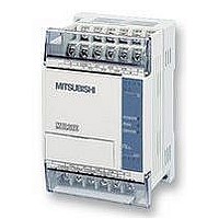
FX1S-30MR-ES/UL MITSUBISHI, FX1S-30MR-ES/UL Datasheet - Page 211

FX1S-30MR-ES/UL
Manufacturer Part Number
FX1S-30MR-ES/UL
Description
PLC, 16 IN, 14 RELAY OUT, 110V/2
Manufacturer
MITSUBISHI
Datasheet
1.FX1S-30MR-ESUL.pdf
(380 pages)
Specifications of FX1S-30MR-ES/UL
No. Of Analogue Inputs
16
No. Of Analogue Outputs
14
Ip/nema Rating
IP10
Approval Bodies
CE, CUL, UL
External Depth
49mm
External Length / Height
90mm
External Width
60mm
Mounting Type
Panel
- Current page: 211 of 380
- Download datasheet (7Mb)
5.8.8
FX Series Programmable Controlers
PR (FNC 77)
destination devices D
numbered in octal) and an execution/busy flag (D
Points to note:
a) The source byte-data maps the lowest bit to the first destination device D
b) The PR instruction may only be used TWICE in a sequence program. This instruction
c) The operation of the PR instruction is program scan dependent. Under standard
d)8 byte operation has the following timing diagram. It
e) 16 byte operation requires the special auxiliary flag
PR
FNC 77
(Print)
Mnemonic
should be noted that when the drive input (in the
example X0) is switched OFF the PR instruction will
ce as e o pe ra tion . W he n it is r es ta rte d th e P R
instruction will start from the beginning of the
message string. Once all 8 bytes have been sent the
execution/busy flag is dropped and the PR instruction
suspends operation.
the highest bit of the byte is sent to destination device D
should only be used on transistor output PLC’s. The PR instruction will not automatically
repeat its operation unless the drive input has been turned OFF and ON again.
circumstances it takes 3 program scans to send 1 byte. However, for a faster operation the
PR instruction could be written into a timer interrupt routine similar to the one demonstrated
for HKY on page 5-82.
M8027 to be driven ON (it is recommended that
M8000 is used as a drive input). In this operation
mode the drive input (in the example X0) does not
have to be active all of the time. Once the PR
instruction is activated it will operate continuously
until all 16 bytes of data have been sent or the value
00H (null) has been sent. Once the operation is
complete the execution/busy flag (D
turned OFF and M8029 the execution complete flag
is set.
Outputs ASCII
data to items
such as display
units
Function
+0
to D
+7
). The final two destination bits provide a strobe signal (D
T, C, D
Note: 8 byte mode (M8027=OFF)
uses 4 consecutive devices
16 byte mode (M8027= ON) uses 8
consecutive devices
+11
Operation:
Source data (stored as ASCII values) is read byte
by byte from the source data devices. Each byte is
m a p p e d d i re c t l y t o t h e f ir s t 8 c o n s e c u t iv e
, octal) is
S
Operands
+11
, in octal).
+7.
Y
Note: uses
10
consecutive
devices.
D
1
Applied Instructions 5
PR:
5 steps
+0.
Program steps
5-89
Consequently
+10
,
Related parts for FX1S-30MR-ES/UL
Image
Part Number
Description
Manufacturer
Datasheet
Request
R

Part Number:
Description:
MITSUBISHI IGBT MODULES
Manufacturer:
MITSUBISHI
Datasheet:

Part Number:
Description:
MITSUBISHI INTELLIGENT POWER MODULES
Manufacturer:
MITSUBISHI
Datasheet:

Part Number:
Description:
TRANSFER-MOLD TYPE INSULATED TYPE
Manufacturer:
MITSUBISHI
Datasheet:

Part Number:
Description:
Manufacturer:
MITSUBISHI
Datasheet:

Part Number:
Description:
30A intelligent power module for flat-base type
Manufacturer:
MITSUBISHI
Datasheet:

Part Number:
Description:
15A - transistor module for medium power switching use, insulated type
Manufacturer:
MITSUBISHI
Datasheet:

Part Number:
Description:
5A power module for transfer-mold type insulated type
Manufacturer:
MITSUBISHI
Datasheet:

Part Number:
Description:
30A intelligent power module for flat-base type
Manufacturer:
MITSUBISHI
Datasheet:

Part Number:
Description:
TRANSFER-MOLD TYPE INSULATED TYPE
Manufacturer:
MITSUBISHI
Datasheet:

Part Number:
Description:
TRANSFER-MOLD TYPE INSULATED TYPE
Manufacturer:
MITSUBISHI
Datasheet:

Part Number:
Description:
20A - transistor module for medium power switching use, insulated type
Manufacturer:
MITSUBISHI
Datasheet:

Part Number:
Description:
20A - transistor module for medium power switching use, insulated type
Manufacturer:
MITSUBISHI
Datasheet:


