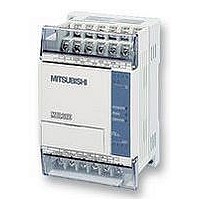
FX1S-30MR-ES/UL MITSUBISHI, FX1S-30MR-ES/UL Datasheet - Page 194

FX1S-30MR-ES/UL
Manufacturer Part Number
FX1S-30MR-ES/UL
Description
PLC, 16 IN, 14 RELAY OUT, 110V/2
Manufacturer
MITSUBISHI
Datasheet
1.FX1S-30MR-ESUL.pdf
(380 pages)
Specifications of FX1S-30MR-ES/UL
No. Of Analogue Inputs
16
No. Of Analogue Outputs
14
Ip/nema Rating
IP10
Approval Bodies
CE, CUL, UL
External Depth
49mm
External Length / Height
90mm
External Width
60mm
Mounting Type
Panel
- Current page: 194 of 380
- Download datasheet (7Mb)
5.7.5
5.7.6
FX Series Programmable Controlers
TTMR (FNC 64)
STMR (FNC 65)
TTMR
FNC 64
(Teaching
timer)
STMR
FNC 65
(Special
timer)
Mnemonic
Mnemonic
Monitors the
duration of a
signal and places
the timed data
into a data regis-
ter
Provides
dedicated
off-delay, one
shot and flash
timers
Function
Function
D
Note:
2 devices 16 bit words
are used D and D
T
Note:
Timers 0 to 199
(100msec
devices)
S
D
Operation:
The duration of time that the TTMR instruction is
energized, is measured and stored in device D
(as a count of 100ms periods).
The data value of D
factor selected by the operand n, is moved in to
register D. The contents of D could be used as the
source data for an indirect timer setting or even as
raw data for manipulation.
When the TTMR instruction is de-energized D
automatically reset (D is unchanged).
Operation:
The designated timer Swill operate for the duration
n with the operational effect being flagged by
devices D+0to D+3. Device D+0is an off-delay
timer, D+1is a one shot timer. When D+3is used in
the configuration below, D+1and D+2act in a
alternate flashing sequence.
K, H
Note:
n=
1 to 32,767
+1
Operands
Operands
n
K, H
Note:
n= 0: (D) = (D
n= 1: (D) = (D
n= 2: (D) = (D
Y, M, S
Note:uses 4
consecutive
devices
D+0to D+3
+1
n
+1
+1
+1
(in secs), multiplied by the
) 1
) 10
) 100
D
Applied Instructions 5
TTMR:
5 steps
STMR:
7 steps
Program steps
Program steps
5-72
+1
+1
is
Related parts for FX1S-30MR-ES/UL
Image
Part Number
Description
Manufacturer
Datasheet
Request
R

Part Number:
Description:
MITSUBISHI IGBT MODULES
Manufacturer:
MITSUBISHI
Datasheet:

Part Number:
Description:
MITSUBISHI INTELLIGENT POWER MODULES
Manufacturer:
MITSUBISHI
Datasheet:

Part Number:
Description:
TRANSFER-MOLD TYPE INSULATED TYPE
Manufacturer:
MITSUBISHI
Datasheet:

Part Number:
Description:
Manufacturer:
MITSUBISHI
Datasheet:

Part Number:
Description:
30A intelligent power module for flat-base type
Manufacturer:
MITSUBISHI
Datasheet:

Part Number:
Description:
15A - transistor module for medium power switching use, insulated type
Manufacturer:
MITSUBISHI
Datasheet:

Part Number:
Description:
5A power module for transfer-mold type insulated type
Manufacturer:
MITSUBISHI
Datasheet:

Part Number:
Description:
30A intelligent power module for flat-base type
Manufacturer:
MITSUBISHI
Datasheet:

Part Number:
Description:
TRANSFER-MOLD TYPE INSULATED TYPE
Manufacturer:
MITSUBISHI
Datasheet:

Part Number:
Description:
TRANSFER-MOLD TYPE INSULATED TYPE
Manufacturer:
MITSUBISHI
Datasheet:

Part Number:
Description:
20A - transistor module for medium power switching use, insulated type
Manufacturer:
MITSUBISHI
Datasheet:

Part Number:
Description:
20A - transistor module for medium power switching use, insulated type
Manufacturer:
MITSUBISHI
Datasheet:


