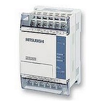
FX1S-30MR-ES/UL MITSUBISHI, FX1S-30MR-ES/UL Datasheet - Page 356

FX1S-30MR-ES/UL
Manufacturer Part Number
FX1S-30MR-ES/UL
Description
PLC, 16 IN, 14 RELAY OUT, 110V/2
Manufacturer
MITSUBISHI
Datasheet
1.FX1S-30MR-ESUL.pdf
(380 pages)
Specifications of FX1S-30MR-ES/UL
No. Of Analogue Inputs
16
No. Of Analogue Outputs
14
Ip/nema Rating
IP10
Approval Bodies
CE, CUL, UL
External Depth
49mm
External Length / Height
90mm
External Width
60mm
Mounting Type
Panel
- Current page: 356 of 380
- Download datasheet (7Mb)
10.15 PID Programming Techniques
10.15.1 Keeping MV within a set range
10.15.2 Manual/Automatic change over
FX Series Programmable Controllers
In the reserved registers of the PID data block S
that contains the previous MV x K100. The following program uses this to keep MV under
control when it exceeds the operating limits.
Example Program to keep MV in the range K100 to K5000
If data registers are used to hold the limit values, it is possible to use a MUL instruction instead
of the DMOV. E.g. When D50 is upper limit use: MUL D50 K100 D38 because the result of
MUL is already a double word DMUL is not needed.
Resetting (S
In order to switch from automatic (PID) control to manual control and back to automatic it is
necessary for the PID process to perform ’Manual Tracking’. Although the FX PID instruction
does not have a manual tracking feature there are two methods that can be used to make the
switch from manual back to automatic as trouble free as possible.
To understand the reason for the two methods the following should be noted. The PID
instruction sets its initial output value based on the initial value of the output register.
When the PID instruction is switched on it can only do P as it has only 1 data reading. On the
first reading the current value of the output register is used as MV. Thereafter the previous
output value is used (stored in S
After the next reading PI can be calculated and from the third reading full PID is performed.
Please see section 5.98, PID (FNC 88), for the complete equations.
Method 1
It is recommended that if manual to auto switching is desired that the PID instruction is
switched off during manual operation and the operator controls the value of the MV register
(the Output Value). When returning to auto mode, the PID instruction is switched on again and
uses the last MV input by the operator during the first PID calculation. After 3 readings full PID
will be operating and the process should be under control quickly. (Assuming that manual
control did not cause a move too far from the Set Point.)
3
+19, S
X10
M20
M22
Lower Limit
Upper Limit
Below
3
Above
+18) in this way prevents runaway, which occurs if only MV is changed.
ZCP
PID
K100
D18
SV
3
+18, S
DMOV
DMOV
K5000
MOV
MOV
D19
PV
K10000
K500000
K5000
Block
K100
Data
D20
D46
3
MV
+19).
MV
MV
K100
D46
M20
D46
D38
D46
K100
MV
MV
MV
D38
n-1
n-1
x
x
3
+18 and S
Check MV against range
MV < 100: Fix MV to lower limit
Reset PID data to lower limit
MV > 5000: Fix MV to upper limit
Reset PID data to upper limit
3
+19 form a double word device
Points Of Technique 10
10-24
Related parts for FX1S-30MR-ES/UL
Image
Part Number
Description
Manufacturer
Datasheet
Request
R

Part Number:
Description:
MITSUBISHI IGBT MODULES
Manufacturer:
MITSUBISHI
Datasheet:

Part Number:
Description:
MITSUBISHI INTELLIGENT POWER MODULES
Manufacturer:
MITSUBISHI
Datasheet:

Part Number:
Description:
TRANSFER-MOLD TYPE INSULATED TYPE
Manufacturer:
MITSUBISHI
Datasheet:

Part Number:
Description:
Manufacturer:
MITSUBISHI
Datasheet:

Part Number:
Description:
30A intelligent power module for flat-base type
Manufacturer:
MITSUBISHI
Datasheet:

Part Number:
Description:
15A - transistor module for medium power switching use, insulated type
Manufacturer:
MITSUBISHI
Datasheet:

Part Number:
Description:
5A power module for transfer-mold type insulated type
Manufacturer:
MITSUBISHI
Datasheet:

Part Number:
Description:
30A intelligent power module for flat-base type
Manufacturer:
MITSUBISHI
Datasheet:

Part Number:
Description:
TRANSFER-MOLD TYPE INSULATED TYPE
Manufacturer:
MITSUBISHI
Datasheet:

Part Number:
Description:
TRANSFER-MOLD TYPE INSULATED TYPE
Manufacturer:
MITSUBISHI
Datasheet:

Part Number:
Description:
20A - transistor module for medium power switching use, insulated type
Manufacturer:
MITSUBISHI
Datasheet:

Part Number:
Description:
20A - transistor module for medium power switching use, insulated type
Manufacturer:
MITSUBISHI
Datasheet:


