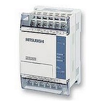
FX1S-30MR-ES/UL MITSUBISHI, FX1S-30MR-ES/UL Datasheet - Page 229

FX1S-30MR-ES/UL
Manufacturer Part Number
FX1S-30MR-ES/UL
Description
PLC, 16 IN, 14 RELAY OUT, 110V/2
Manufacturer
MITSUBISHI
Datasheet
1.FX1S-30MR-ESUL.pdf
(380 pages)
Specifications of FX1S-30MR-ES/UL
No. Of Analogue Inputs
16
No. Of Analogue Outputs
14
Ip/nema Rating
IP10
Approval Bodies
CE, CUL, UL
External Depth
49mm
External Length / Height
90mm
External Width
60mm
Mounting Type
Panel
- Current page: 229 of 380
- Download datasheet (7Mb)
FX Series Programmable Controlers
Example PID Settings
The partial program shown at below demonstrates which parameters must be set for the
functioning of the FX2N. The first step sets the user values for S
instruction will be activated when M4 is On.
From the PID instruction at the bottom of the ladder, S
or MV = D525.
D500: Ts = 500 ms
D501: Forward Operation,
Alarms Not Enabled
D502: Input Filter = 50%
D503: K
D504: T
D505: K
D506: T
D200: Set Point = 1000
D201: PV
input value)
Begin the PID instruction
D525: PID Output Value
I
D
P
D
= 4000 ms
= 1000 ms
nf
= 75%
= 50%
(an analog
M8002
M8002
M1
M4
FNC 79
FNC 78
FNC 88
FROM
TO
PID
1
= D200; S
D200
K2
K2
FNC 12
MOV
FNC 12
MOV
FNC 12
MOV
FNC 12
MOV
FNC 12
MOV
FNC 12
MOV
FNC 12
MOV
FNC 12
MOV
2
D201
K1
K5
= D201; S
P
P
P
P
P
P
P
P
3
+0 to S
K 1000 D200
H0000 D501
K2000 D504
K3000 D506
D201
D500
K500
K50
K75
K50
K4
Applied Instructions 5
3
D500
D502
D503
D505
D525
5-107
K4
K4
3
= D500; and D
+6. The PID
Related parts for FX1S-30MR-ES/UL
Image
Part Number
Description
Manufacturer
Datasheet
Request
R

Part Number:
Description:
MITSUBISHI IGBT MODULES
Manufacturer:
MITSUBISHI
Datasheet:

Part Number:
Description:
MITSUBISHI INTELLIGENT POWER MODULES
Manufacturer:
MITSUBISHI
Datasheet:

Part Number:
Description:
TRANSFER-MOLD TYPE INSULATED TYPE
Manufacturer:
MITSUBISHI
Datasheet:

Part Number:
Description:
Manufacturer:
MITSUBISHI
Datasheet:

Part Number:
Description:
30A intelligent power module for flat-base type
Manufacturer:
MITSUBISHI
Datasheet:

Part Number:
Description:
15A - transistor module for medium power switching use, insulated type
Manufacturer:
MITSUBISHI
Datasheet:

Part Number:
Description:
5A power module for transfer-mold type insulated type
Manufacturer:
MITSUBISHI
Datasheet:

Part Number:
Description:
30A intelligent power module for flat-base type
Manufacturer:
MITSUBISHI
Datasheet:

Part Number:
Description:
TRANSFER-MOLD TYPE INSULATED TYPE
Manufacturer:
MITSUBISHI
Datasheet:

Part Number:
Description:
TRANSFER-MOLD TYPE INSULATED TYPE
Manufacturer:
MITSUBISHI
Datasheet:

Part Number:
Description:
20A - transistor module for medium power switching use, insulated type
Manufacturer:
MITSUBISHI
Datasheet:

Part Number:
Description:
20A - transistor module for medium power switching use, insulated type
Manufacturer:
MITSUBISHI
Datasheet:


