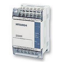
FX1S-30MR-ES/UL MITSUBISHI, FX1S-30MR-ES/UL Datasheet - Page 175

FX1S-30MR-ES/UL
Manufacturer Part Number
FX1S-30MR-ES/UL
Description
PLC, 16 IN, 14 RELAY OUT, 110V/2
Manufacturer
MITSUBISHI
Datasheet
1.FX1S-30MR-ESUL.pdf
(380 pages)
Specifications of FX1S-30MR-ES/UL
No. Of Analogue Inputs
16
No. Of Analogue Outputs
14
Ip/nema Rating
IP10
Approval Bodies
CE, CUL, UL
External Depth
49mm
External Length / Height
90mm
External Width
60mm
Mounting Type
Panel
- Current page: 175 of 380
- Download datasheet (7Mb)
5.6.1
5.6.2
FX Series Programmable Controlers
Note: A short delay will occur before the I/O device is physically updated, in the case of inputs
a time equivalent to the filter setting, while outputs will delay for their set energized time.
REF (FNC 50)
the REF instruction is used. The REF instruction can only be used to update or refresh blocks of
8 (n) consecutive devices. The head address of the refreshed devices should always have its
last digit as a 0 (zero), i.e. in units of 10.
REFF (FNC 51)
input filters slows down the PLC response times. For high speed applications, especially where
solid state switching provides the input signal, input filter times may be reduced. The default
setting for the input filters is approximately 10 msec. Using this instruction input filter times of 0
to 60 msec may be selected. The setting ‘0’ (zero) is actually 50 sec. This is the minimum
available setting. It is automatically selected when direct input, interrupts or high speed counting
functions are used. The REFF instruction needs to be driven for each program scan if it is to be
effective, otherwise, the standard 10 msec filter time is used.
REF
FNC 50
(
REFF
FNC 51
(Refresh
and filter
adjust)
Refresh)
Mnemonic
Mnemonic
å
Forces an
immediate update
of inputs or
outputs as
specified
Inputs are
refreshed, and
their input filters
are reset to the
newly designated
value
Function
Function
X, Y
Note:
D should always be a
multiple of 10, i.e. 00,
10, 20, 30 etc.
K, H,
Note: n= 0 to 60 msec (0 = 50 s)
X000 to X007 (X000 to X017 for FX
automatically designated when using this
instruction
Operation :
PLC’s are provided with input filters to overcome
problems generated by mechanical switch gear.
However, as this involves ensuring a steady input
signal is received for a fixed time duration, the use of
Operation :
Standard PLC operation processes output and input
status between the END instruction of one program
scan and step 0 of the following program scan. If an
immediate update of the I/O device status is required
D
Operands
Operands
n
K, H
Note:
n should always be a
multiple of 8, i.e. 8, 16,
24, 32 etc.
n
2N
) are
Applied Instructions 5
REF, REFP:
5 steps
REFF,
REFFP:
3 steps
Program steps
Program steps
5-53
Related parts for FX1S-30MR-ES/UL
Image
Part Number
Description
Manufacturer
Datasheet
Request
R

Part Number:
Description:
MITSUBISHI IGBT MODULES
Manufacturer:
MITSUBISHI
Datasheet:

Part Number:
Description:
MITSUBISHI INTELLIGENT POWER MODULES
Manufacturer:
MITSUBISHI
Datasheet:

Part Number:
Description:
TRANSFER-MOLD TYPE INSULATED TYPE
Manufacturer:
MITSUBISHI
Datasheet:

Part Number:
Description:
Manufacturer:
MITSUBISHI
Datasheet:

Part Number:
Description:
30A intelligent power module for flat-base type
Manufacturer:
MITSUBISHI
Datasheet:

Part Number:
Description:
15A - transistor module for medium power switching use, insulated type
Manufacturer:
MITSUBISHI
Datasheet:

Part Number:
Description:
5A power module for transfer-mold type insulated type
Manufacturer:
MITSUBISHI
Datasheet:

Part Number:
Description:
30A intelligent power module for flat-base type
Manufacturer:
MITSUBISHI
Datasheet:

Part Number:
Description:
TRANSFER-MOLD TYPE INSULATED TYPE
Manufacturer:
MITSUBISHI
Datasheet:

Part Number:
Description:
TRANSFER-MOLD TYPE INSULATED TYPE
Manufacturer:
MITSUBISHI
Datasheet:

Part Number:
Description:
20A - transistor module for medium power switching use, insulated type
Manufacturer:
MITSUBISHI
Datasheet:

Part Number:
Description:
20A - transistor module for medium power switching use, insulated type
Manufacturer:
MITSUBISHI
Datasheet:


