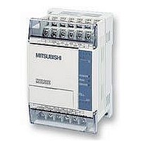
FX1S-30MR-ES/UL MITSUBISHI, FX1S-30MR-ES/UL Datasheet - Page 54

FX1S-30MR-ES/UL
Manufacturer Part Number
FX1S-30MR-ES/UL
Description
PLC, 16 IN, 14 RELAY OUT, 110V/2
Manufacturer
MITSUBISHI
Datasheet
1.FX1S-30MR-ESUL.pdf
(380 pages)
Specifications of FX1S-30MR-ES/UL
No. Of Analogue Inputs
16
No. Of Analogue Outputs
14
Ip/nema Rating
IP10
Approval Bodies
CE, CUL, UL
External Depth
49mm
External Length / Height
90mm
External Width
60mm
Mounting Type
Panel
- Current page: 54 of 380
- Download datasheet (7Mb)
3.2
3.2.1
FX Series Programmable Controllers
How STL Operates
As previously mentioned, STL is a system which
allows the user to write a program which functions
in much the same way as a flow chart, this can be
seen in the diagram opposite.
STL derives its strength by organizing a larger
program into smaller more manageable parts.
Each of these parts can be referred to as either a
state or a step. To help identify the states, each is
given a unique identification number. These
numbers are taken from the state relay devices
(see page 4-6 for more details).
Each step is a program
Each state is completely isolated from all other states within the whole program. A good way to
envisage this, is that each state is a separate program and the user puts each of those
programs together in the order that they require to perform their task. Immediately this means
that states can be reused many times and in different orders. This saves on programming time
AND cuts down on the number of programming errors encountered.
A Look Inside an STL
On initial inspection the STL program looks as if it is a rather basic flow diagram. But to find out
what is really happening the STL state needs to be put ‘under a microscope’ so to speak.
When a single state is examined in more detail, the sub-program can be viewed.
With the exception of the STL instruction, it will be
immediately seen that the STL sub-program looks
just like ordinary programming.
This idea re-enforces the concept that STL is really
a method of sequencing a series of events or as
mentioned earlier ‘of joining lots of sm aller
programs together’.
The STL instruction is shown as a ‘fat’ normally
open contact.
All programming after an STL instruction is only
active when the associated state coil is active.
The transition condition is also written using
standard programming.
M8002
STL
S 22
X0
X1
T0
T7
S 22
S 0
S 27
1
2
1
T0
S 22
T0
STL Programming 3
SET S 27
2
3-2
Y22
X15
T0
X0
X1
K20
S 26
Related parts for FX1S-30MR-ES/UL
Image
Part Number
Description
Manufacturer
Datasheet
Request
R

Part Number:
Description:
MITSUBISHI IGBT MODULES
Manufacturer:
MITSUBISHI
Datasheet:

Part Number:
Description:
MITSUBISHI INTELLIGENT POWER MODULES
Manufacturer:
MITSUBISHI
Datasheet:

Part Number:
Description:
TRANSFER-MOLD TYPE INSULATED TYPE
Manufacturer:
MITSUBISHI
Datasheet:

Part Number:
Description:
Manufacturer:
MITSUBISHI
Datasheet:

Part Number:
Description:
30A intelligent power module for flat-base type
Manufacturer:
MITSUBISHI
Datasheet:

Part Number:
Description:
15A - transistor module for medium power switching use, insulated type
Manufacturer:
MITSUBISHI
Datasheet:

Part Number:
Description:
5A power module for transfer-mold type insulated type
Manufacturer:
MITSUBISHI
Datasheet:

Part Number:
Description:
30A intelligent power module for flat-base type
Manufacturer:
MITSUBISHI
Datasheet:

Part Number:
Description:
TRANSFER-MOLD TYPE INSULATED TYPE
Manufacturer:
MITSUBISHI
Datasheet:

Part Number:
Description:
TRANSFER-MOLD TYPE INSULATED TYPE
Manufacturer:
MITSUBISHI
Datasheet:

Part Number:
Description:
20A - transistor module for medium power switching use, insulated type
Manufacturer:
MITSUBISHI
Datasheet:

Part Number:
Description:
20A - transistor module for medium power switching use, insulated type
Manufacturer:
MITSUBISHI
Datasheet:


