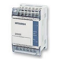
FX1S-30MR-ES/UL MITSUBISHI, FX1S-30MR-ES/UL Datasheet - Page 204

FX1S-30MR-ES/UL
Manufacturer Part Number
FX1S-30MR-ES/UL
Description
PLC, 16 IN, 14 RELAY OUT, 110V/2
Manufacturer
MITSUBISHI
Datasheet
1.FX1S-30MR-ESUL.pdf
(380 pages)
Specifications of FX1S-30MR-ES/UL
No. Of Analogue Inputs
16
No. Of Analogue Outputs
14
Ip/nema Rating
IP10
Approval Bodies
CE, CUL, UL
External Depth
49mm
External Length / Height
90mm
External Width
60mm
Mounting Type
Panel
- Current page: 204 of 380
- Download datasheet (7Mb)
5.8.2
FX Series Programmable Controlers
HKY (FNC 71)
Points to note:
a) Each of the first 10 multiplexed source devices (identified as 0 to 9) map directly to decimal
b) The last 6 multiplexed source devices (identified as function keys A to F) are used to set bit
c) In all key entry cases, when two or more keys are pressed, only the key activated first is
d) When the HKY instruction is used with 16 bit
HKY
FNC 71
(Hexadeci-
mal
key input)
Mnemonic
values 0 to 9. When entered, i.e. a source device is activated, then its associated decimal
value is added to the data string currently stored in D
causes bit device D
devices D
function key has been activated. Activation of any of these keys causes bit device D
turn ON for the duration of that key press.
effective. When the pressing of a key is sensed the M8029 (execution complete flag) is
turned ON. When the HKY instruction is OFF, all D
remains intact.
operation, D
i.e. max. 4 digits. When the DHKY instruction is
used (32 bit operation) values of 0 to 99,999,999
(max. 8 digits) can be accommodated in two
consecutive devices D
the number to be stored exceeds the allowable
ranges, the highest digits will overflow until an
allowable number is reached. The over-flowed
digits are lost and can no longer be accessed by
the user. Leading zero’s are not accommodated,
i.e. 0127 will actually be stored as 127 only. This
operation is similar to that of the TKY instruction.
3+0
Multiplexes inputs
and outputs to
create a numeric
keyboard with 6
function keys
2
to D
can store numbers from 0 to 9,999
Function
3+5
3+7
respectively. These bit flags, once set ON, remain ON until the next
to turn ON for the duration of that key press.
2
and D
X,
Note:
uses 4
consecu-
tive
devices
2+1
S
. In both cases if
Y,
Note:
uses 4
consecu-
tive
devices
Operation 1 - Standard:
This instruction creates a multiplex of 4 outputs
(D
devices. Decimal values of 0 to 9 can be stored
while 6 further function flags may be set.
D
1
) and 4 inputs (S) to read in 16 different
1
Operands
T, C, D, V, Z
Note: uses 2
consecutive
devices
for 32 bit
operation
3
devices are reset but data value D
D
2
2
. Activation of any of these keys
Y, M, S
Note:
uses 8
consecu-
tive
devices
D
3
Applied Instructions 5
HKY:
9 steps
DHKY:
17 steps
Program steps
5-82
3+6
to
2
Related parts for FX1S-30MR-ES/UL
Image
Part Number
Description
Manufacturer
Datasheet
Request
R

Part Number:
Description:
MITSUBISHI IGBT MODULES
Manufacturer:
MITSUBISHI
Datasheet:

Part Number:
Description:
MITSUBISHI INTELLIGENT POWER MODULES
Manufacturer:
MITSUBISHI
Datasheet:

Part Number:
Description:
TRANSFER-MOLD TYPE INSULATED TYPE
Manufacturer:
MITSUBISHI
Datasheet:

Part Number:
Description:
Manufacturer:
MITSUBISHI
Datasheet:

Part Number:
Description:
30A intelligent power module for flat-base type
Manufacturer:
MITSUBISHI
Datasheet:

Part Number:
Description:
15A - transistor module for medium power switching use, insulated type
Manufacturer:
MITSUBISHI
Datasheet:

Part Number:
Description:
5A power module for transfer-mold type insulated type
Manufacturer:
MITSUBISHI
Datasheet:

Part Number:
Description:
30A intelligent power module for flat-base type
Manufacturer:
MITSUBISHI
Datasheet:

Part Number:
Description:
TRANSFER-MOLD TYPE INSULATED TYPE
Manufacturer:
MITSUBISHI
Datasheet:

Part Number:
Description:
TRANSFER-MOLD TYPE INSULATED TYPE
Manufacturer:
MITSUBISHI
Datasheet:

Part Number:
Description:
20A - transistor module for medium power switching use, insulated type
Manufacturer:
MITSUBISHI
Datasheet:

Part Number:
Description:
20A - transistor module for medium power switching use, insulated type
Manufacturer:
MITSUBISHI
Datasheet:


