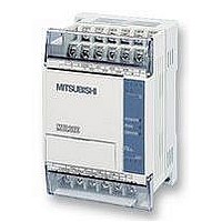
FX1S-30MR-ES/UL MITSUBISHI, FX1S-30MR-ES/UL Datasheet - Page 126

FX1S-30MR-ES/UL
Manufacturer Part Number
FX1S-30MR-ES/UL
Description
PLC, 16 IN, 14 RELAY OUT, 110V/2
Manufacturer
MITSUBISHI
Datasheet
1.FX1S-30MR-ESUL.pdf
(380 pages)
Specifications of FX1S-30MR-ES/UL
No. Of Analogue Inputs
16
No. Of Analogue Outputs
14
Ip/nema Rating
IP10
Approval Bodies
CE, CUL, UL
External Depth
49mm
External Length / Height
90mm
External Width
60mm
Mounting Type
Panel
- Current page: 126 of 380
- Download datasheet (7Mb)
5.1
FX Series Programmable Controlers
Program Flow-Functions 00 to 09
Contents:
CJ -
CALL -
SRET -
IRET -
EI -
DI -
FEND -
WDT -
FOR -
NEXT -
Symbols list:
D - Destination device.
S - Source device.
m, n- Number of active devices, bits or an operational constant.
Additional numeric suffixes will be attached if there are more than one operand with the same
function e.g. D
MSB - Most Significant Bit, sometimes used to indicate the mathematical sign of a number,
i.e. positive = 0, and negative = 1.
LSB - Least Significant Bit.
Instruction modifications:
D
D
- An operand which cannot be indexed, i.e. The addition of V or Z is either invalid or will
- A repetitive instruction which will change the destination value on every scan unless
modified by the pulse function.
have no effect to the value of the operand.
P -
-
P - A 32 bit mode instruction modified to use pulse (single) operation.
-
An instruction operating in 16 bit mode, where
mnemonic.
A 16 bit mode instruction modified to use pulse (single) operation.
An instruction modified to operate in 32 bit operation.
1
, S
Conditional jump
Call Subroutine
Subroutine Return
Interrupt Return
Enable Interrupt
Disable Interrupt
First End
Watchdog Timer
Start of a For/Next Loop
End a For/Next Loop
3
or for lists/tabled devices D
3+0,
FNC 00
FNC 01
FNC 02
FNC 03
FNC 04
FNC 05
FNC 06
FNC 07
FNC 08
FNC 09
S
+9
etc.
identifies the instruction
Applied Instructions 5
Page
5-5
5-9
5-9
5-11
5-12
5-13
5-13
5-7
5-8
5-9
5-4
Related parts for FX1S-30MR-ES/UL
Image
Part Number
Description
Manufacturer
Datasheet
Request
R

Part Number:
Description:
MITSUBISHI IGBT MODULES
Manufacturer:
MITSUBISHI
Datasheet:

Part Number:
Description:
MITSUBISHI INTELLIGENT POWER MODULES
Manufacturer:
MITSUBISHI
Datasheet:

Part Number:
Description:
TRANSFER-MOLD TYPE INSULATED TYPE
Manufacturer:
MITSUBISHI
Datasheet:

Part Number:
Description:
Manufacturer:
MITSUBISHI
Datasheet:

Part Number:
Description:
30A intelligent power module for flat-base type
Manufacturer:
MITSUBISHI
Datasheet:

Part Number:
Description:
15A - transistor module for medium power switching use, insulated type
Manufacturer:
MITSUBISHI
Datasheet:

Part Number:
Description:
5A power module for transfer-mold type insulated type
Manufacturer:
MITSUBISHI
Datasheet:

Part Number:
Description:
30A intelligent power module for flat-base type
Manufacturer:
MITSUBISHI
Datasheet:

Part Number:
Description:
TRANSFER-MOLD TYPE INSULATED TYPE
Manufacturer:
MITSUBISHI
Datasheet:

Part Number:
Description:
TRANSFER-MOLD TYPE INSULATED TYPE
Manufacturer:
MITSUBISHI
Datasheet:

Part Number:
Description:
20A - transistor module for medium power switching use, insulated type
Manufacturer:
MITSUBISHI
Datasheet:

Part Number:
Description:
20A - transistor module for medium power switching use, insulated type
Manufacturer:
MITSUBISHI
Datasheet:


