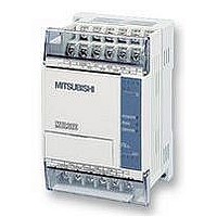
FX1S-30MR-ES/UL MITSUBISHI, FX1S-30MR-ES/UL Datasheet - Page 157

FX1S-30MR-ES/UL
Manufacturer Part Number
FX1S-30MR-ES/UL
Description
PLC, 16 IN, 14 RELAY OUT, 110V/2
Manufacturer
MITSUBISHI
Datasheet
1.FX1S-30MR-ESUL.pdf
(380 pages)
Specifications of FX1S-30MR-ES/UL
No. Of Analogue Inputs
16
No. Of Analogue Outputs
14
Ip/nema Rating
IP10
Approval Bodies
CE, CUL, UL
External Depth
49mm
External Length / Height
90mm
External Width
60mm
Mounting Type
Panel
- Current page: 157 of 380
- Download datasheet (7Mb)
5.4.1
5.4.2
FX Series Programmable Controlers
ROR (FNC 30)
ROL (FNC 31)
ROR
FNC 30
(Rotation
right)
ROL
FNC 31
(Rotation
left)
Mnemonic
Mnemonic
The bit pattern of
the destination
device is rotated
‘n’ places to the
right on every
execution
The bit pattern of
the destination
device is rotated
‘n’ places to the
left on every
execution
Function
Function
KnY, KnM, KnS,
T, C, D, V, Z
Note:
16 bit operation
Kn=K4,
32 bit operation Kn=K8
KnY, KnM, KnS,
T, C, D, V, Z
Note:
16 bit operation
Kn= K4,
32 bit operation
Kn= K8
Operation :
The bit pattern of the destination device (D) is rotated
n bit places to the right on every operation of the
instruction.
The status of the last bit rotated is copied to the carry
flag M8022.
The example shown left is based on the instruction
noted above it, where the bit pattern represents the
contents of D0.
Operation :
The bit pattern of the destination device (D) is rotated
n bit places to the left on every operation of the
instruction.
The status of the last bit rotated is copied to the carry
flag M8022.
The example shown left is based on the instruction
noted above it, where the bit pattern represents the
contents of D0.
S
D
Operands
Operands
K, H,
Note:
16 bit operation n
32 bit operation n 32
K, H,
Note:
16 bit operation n 16
32 bit operation n 32
D
n
16
Applied Instructions 5
ROR, RORP:
5 steps
DROR,
DRORP:
9 steps
ROL,ROLP:
5 steps
DROL,
DROLP:
7 steps
Program steps
Program steps
5-35
Related parts for FX1S-30MR-ES/UL
Image
Part Number
Description
Manufacturer
Datasheet
Request
R

Part Number:
Description:
MITSUBISHI IGBT MODULES
Manufacturer:
MITSUBISHI
Datasheet:

Part Number:
Description:
MITSUBISHI INTELLIGENT POWER MODULES
Manufacturer:
MITSUBISHI
Datasheet:

Part Number:
Description:
TRANSFER-MOLD TYPE INSULATED TYPE
Manufacturer:
MITSUBISHI
Datasheet:

Part Number:
Description:
Manufacturer:
MITSUBISHI
Datasheet:

Part Number:
Description:
30A intelligent power module for flat-base type
Manufacturer:
MITSUBISHI
Datasheet:

Part Number:
Description:
15A - transistor module for medium power switching use, insulated type
Manufacturer:
MITSUBISHI
Datasheet:

Part Number:
Description:
5A power module for transfer-mold type insulated type
Manufacturer:
MITSUBISHI
Datasheet:

Part Number:
Description:
30A intelligent power module for flat-base type
Manufacturer:
MITSUBISHI
Datasheet:

Part Number:
Description:
TRANSFER-MOLD TYPE INSULATED TYPE
Manufacturer:
MITSUBISHI
Datasheet:

Part Number:
Description:
TRANSFER-MOLD TYPE INSULATED TYPE
Manufacturer:
MITSUBISHI
Datasheet:

Part Number:
Description:
20A - transistor module for medium power switching use, insulated type
Manufacturer:
MITSUBISHI
Datasheet:

Part Number:
Description:
20A - transistor module for medium power switching use, insulated type
Manufacturer:
MITSUBISHI
Datasheet:


