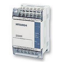
FX1S-30MR-ES/UL MITSUBISHI, FX1S-30MR-ES/UL Datasheet - Page 342

FX1S-30MR-ES/UL
Manufacturer Part Number
FX1S-30MR-ES/UL
Description
PLC, 16 IN, 14 RELAY OUT, 110V/2
Manufacturer
MITSUBISHI
Datasheet
1.FX1S-30MR-ESUL.pdf
(380 pages)
Specifications of FX1S-30MR-ES/UL
No. Of Analogue Inputs
16
No. Of Analogue Outputs
14
Ip/nema Rating
IP10
Approval Bodies
CE, CUL, UL
External Depth
49mm
External Length / Height
90mm
External Width
60mm
Mounting Type
Panel
- Current page: 342 of 380
- Download datasheet (7Mb)
FX Series Programmable Controllers
Points Of Technique 10
This example uses the IST instruction (FNC 60) to
control the operation mode of the robot arm. The
program shown opposite identifies how the IST
instruction is written into the main program.
When the IST instruction is used there are 5
selectable modes which access three separate
p r o g r a m s . T h i s e x a m p l e h a s t h e f o l l o w i n g
programs associated with its modes. Each mode is
selected through the FX-40DU-TK. The screen
shown opposite is the initial mode menu. Each of
the menu options causes a screen jump to the
selected mode. Menu options 1 and 3 also set ON
auxiliary devices M30 and M31 respectively.
The active bits then trigger a screen change to the
selected mode. Please note ’Automatic’ has three
further modes which are selected from a following
screen/display.
Manual Mode:
In this mode ALL operations of the robot arm are
con tro lled by the op erator. An ope ration or
m o v e m e n t i s s e l e c t e d b y p r e s s i n g t h e
corresponding option on the DUs screen (see
below). These options then trigger DU SWITCH
objects which drive associated auxiliary relays
within the programmable controller. The SWITCH
objects should be set to momentary so that they
only operate when the key is pressed.
The s ta tu s of th e c lam ping ac tio n cou ld b e
identified by two INDICATOR (SCR) functions on
the DU unit. They could be monitoring the ON and
OFF status of the clamp output Y1. Hence, when
the clamp was ON a single black box opposite the
ON button could appear. When the clamp is OFF
the box would appear in front of the OFF button. At
any one time only one box would be active.
Key assignment for DU screen opposite:
Up = M15 Down = M20
Left = M16 Right = M21
Clamp ON = M22
Clamp OFF = M17
Menu = reset M30
Once manual operation is completed the operator can return to the main mode selection
screen by touching the ’Menu’ key. This causes the manual mode bit flag, M30, to be reset.
Once M30 is reset the DU screen then changes back to the desired mode selection screen.
10-10
Related parts for FX1S-30MR-ES/UL
Image
Part Number
Description
Manufacturer
Datasheet
Request
R

Part Number:
Description:
MITSUBISHI IGBT MODULES
Manufacturer:
MITSUBISHI
Datasheet:

Part Number:
Description:
MITSUBISHI INTELLIGENT POWER MODULES
Manufacturer:
MITSUBISHI
Datasheet:

Part Number:
Description:
TRANSFER-MOLD TYPE INSULATED TYPE
Manufacturer:
MITSUBISHI
Datasheet:

Part Number:
Description:
Manufacturer:
MITSUBISHI
Datasheet:

Part Number:
Description:
30A intelligent power module for flat-base type
Manufacturer:
MITSUBISHI
Datasheet:

Part Number:
Description:
15A - transistor module for medium power switching use, insulated type
Manufacturer:
MITSUBISHI
Datasheet:

Part Number:
Description:
5A power module for transfer-mold type insulated type
Manufacturer:
MITSUBISHI
Datasheet:

Part Number:
Description:
30A intelligent power module for flat-base type
Manufacturer:
MITSUBISHI
Datasheet:

Part Number:
Description:
TRANSFER-MOLD TYPE INSULATED TYPE
Manufacturer:
MITSUBISHI
Datasheet:

Part Number:
Description:
TRANSFER-MOLD TYPE INSULATED TYPE
Manufacturer:
MITSUBISHI
Datasheet:

Part Number:
Description:
20A - transistor module for medium power switching use, insulated type
Manufacturer:
MITSUBISHI
Datasheet:

Part Number:
Description:
20A - transistor module for medium power switching use, insulated type
Manufacturer:
MITSUBISHI
Datasheet:


