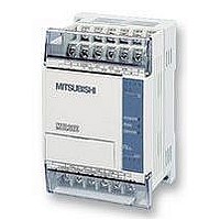
FX1S-30MR-ES/UL MITSUBISHI, FX1S-30MR-ES/UL Datasheet - Page 176

FX1S-30MR-ES/UL
Manufacturer Part Number
FX1S-30MR-ES/UL
Description
PLC, 16 IN, 14 RELAY OUT, 110V/2
Manufacturer
MITSUBISHI
Datasheet
1.FX1S-30MR-ESUL.pdf
(380 pages)
Specifications of FX1S-30MR-ES/UL
No. Of Analogue Inputs
16
No. Of Analogue Outputs
14
Ip/nema Rating
IP10
Approval Bodies
CE, CUL, UL
External Depth
49mm
External Length / Height
90mm
External Width
60mm
Mounting Type
Panel
- Current page: 176 of 380
- Download datasheet (7Mb)
5.6.3
FX Series Programmable Controlers
resistors are required on the drive outputs to
ensure the high speed reading does not detect
any residual currents from the last operation.
These should be placed in parallel to the input
bank and should be of a value of approximately
3.3k , 0.5W. For easier use, high speed inputs
should not be specified at S.
If high speed inputs (ex. X0) is specified for operand S, the reading time of each bank
reading speed. However, additional pull down
becomes only 10msec, i.e. a halving of the
MTR (FNC 52)
processed. The result is stored in a matrix-table (head address D
Points to note:
a) The MTR instruction involves high speed input/output switching. For this reason this
b) For the MTR instruction to operate correctly, it must be driven continuously. It is
c) Each set of 8 input signals are grouped into a ‘bank’ (there are n number of banks).
d) Each bank is triggered/selected by a dedicated output (head address D
e) The matrix instruction operates on an interrupt format, processing each bank of inputs
MTR
FNC 52
(Input
matrix)
Mnemonic
instruction is only recommended for use with transistor output modules.
recommended that special auxiliary relay M8000, the PLC RUN status flag, is used. After
the completion of the first full reading of the matrix, operation complete flag M8029 is turned
ON. This flag is automatically reset when the MTR instruction is turned OFF.
quantity of outputs from D
As there are now additional inputs entering the PLC these will each have a status which
needs recording. This is stored in a matrix-table. The matrix-table starts at the head address
D
a certain input in a selected bank is read, its status is stored in an equivalent position within
the result matrix-table.
every 20msec. This time is based on the selected input filters being set at 10msec. This
would result in an 8 bank matrix, i.e. 64 inputs (8 inputs´ 8 banks) being read in 160msec.
2
. The matrix construction mimics the same 8 signal by n bank configuration. Hence, when
Multiplexes a
bank of inputs
into a number of
sets of devices.
Can only be used
ONCE
Function
1
, used to achieve the matrix are equal to the number of banks n.
X
Note:
These operands should always be
a multiple of 10, i.e. 00, 10, 20, 30
etc.
S
Y
Operation :
This instruction allows a selection of 8 consecutive
input devices (head address S) to be used multiple
(n) times, i.e. each physical input has more than
one, separate and quite different (D
D
1
Operands
Y, M, S
D
2
2
K, H,
Note:
n=2 to 8
).
n
Applied Instructions 5
1
). This means the
MTR: 9 steps
Program steps
1
5-54
) signal being
Related parts for FX1S-30MR-ES/UL
Image
Part Number
Description
Manufacturer
Datasheet
Request
R

Part Number:
Description:
MITSUBISHI IGBT MODULES
Manufacturer:
MITSUBISHI
Datasheet:

Part Number:
Description:
MITSUBISHI INTELLIGENT POWER MODULES
Manufacturer:
MITSUBISHI
Datasheet:

Part Number:
Description:
TRANSFER-MOLD TYPE INSULATED TYPE
Manufacturer:
MITSUBISHI
Datasheet:

Part Number:
Description:
Manufacturer:
MITSUBISHI
Datasheet:

Part Number:
Description:
30A intelligent power module for flat-base type
Manufacturer:
MITSUBISHI
Datasheet:

Part Number:
Description:
15A - transistor module for medium power switching use, insulated type
Manufacturer:
MITSUBISHI
Datasheet:

Part Number:
Description:
5A power module for transfer-mold type insulated type
Manufacturer:
MITSUBISHI
Datasheet:

Part Number:
Description:
30A intelligent power module for flat-base type
Manufacturer:
MITSUBISHI
Datasheet:

Part Number:
Description:
TRANSFER-MOLD TYPE INSULATED TYPE
Manufacturer:
MITSUBISHI
Datasheet:

Part Number:
Description:
TRANSFER-MOLD TYPE INSULATED TYPE
Manufacturer:
MITSUBISHI
Datasheet:

Part Number:
Description:
20A - transistor module for medium power switching use, insulated type
Manufacturer:
MITSUBISHI
Datasheet:

Part Number:
Description:
20A - transistor module for medium power switching use, insulated type
Manufacturer:
MITSUBISHI
Datasheet:


