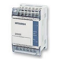
FX1S-30MR-ES/UL MITSUBISHI, FX1S-30MR-ES/UL Datasheet - Page 202

FX1S-30MR-ES/UL
Manufacturer Part Number
FX1S-30MR-ES/UL
Description
PLC, 16 IN, 14 RELAY OUT, 110V/2
Manufacturer
MITSUBISHI
Datasheet
1.FX1S-30MR-ESUL.pdf
(380 pages)
Specifications of FX1S-30MR-ES/UL
No. Of Analogue Inputs
16
No. Of Analogue Outputs
14
Ip/nema Rating
IP10
Approval Bodies
CE, CUL, UL
External Depth
49mm
External Length / Height
90mm
External Width
60mm
Mounting Type
Panel
- Current page: 202 of 380
- Download datasheet (7Mb)
5.8
FX Series Programmable Controlers
External FX I/O Devices - Functions 70 to 79
Contents:
TKY -
HKY -
DSW -
SEGD -
SEGL -
ARWS -
ASC -
PR-
FROM -
TO -
Symbols list:
D - Destination device.
S - Source device.
m, n- Number of active devices, bits or an operational constant.
Additional numeric suffixes will be attached if there are more than one operand with the same
function e.g. D
MSB - Most Significant Bit, sometimes used to indicate the mathematical sign of a number,
i.e. positive = 0, and negative = 1.
LSB - Least Significant Bit.
Instruction modifications:
D
D
- An operand which cannot be indexed, i.e. The addition of V or Z is either invalid or will
- A repetitive instruction which will change the destination value on every scan unless
modified by the pulse function.
have no effect to the value of the operand.
P -
-
P - A 32 bit mode instruction modified to use pulse (single) operation.
-
An instruction operating in 16 bit mode, where
mnemonic.
A 16 bit mode instruction modified to use pulse (single) operation.
An instruction modified to operate in 32 bit operation.
1
, S
Ten Key Input
Hexadecimal Input
Digital Switch
(Thumbwheel input)
Seven Segment Decoder
Seven Segment
With Latch
Arrow Switch
ASCII Code
‘Print’ To A Display
Read From A Special
Function Block
Write To A Special
Function Block
3
or for lists/tabled devices D
3+0,
FNC 70
FNC 71
FNC 72
FNC 73
FNC 74
FNC 75
FNC 76
FNC 77
FNC 78
FNC 79
S
+9
etc.
identifies the instruction
Applied Instructions 5
Page
5-81
5-82
5-83
5-84
5-87
5-88
5-89
5-90
5-91
5-85
5-80
Related parts for FX1S-30MR-ES/UL
Image
Part Number
Description
Manufacturer
Datasheet
Request
R

Part Number:
Description:
MITSUBISHI IGBT MODULES
Manufacturer:
MITSUBISHI
Datasheet:

Part Number:
Description:
MITSUBISHI INTELLIGENT POWER MODULES
Manufacturer:
MITSUBISHI
Datasheet:

Part Number:
Description:
TRANSFER-MOLD TYPE INSULATED TYPE
Manufacturer:
MITSUBISHI
Datasheet:

Part Number:
Description:
Manufacturer:
MITSUBISHI
Datasheet:

Part Number:
Description:
30A intelligent power module for flat-base type
Manufacturer:
MITSUBISHI
Datasheet:

Part Number:
Description:
15A - transistor module for medium power switching use, insulated type
Manufacturer:
MITSUBISHI
Datasheet:

Part Number:
Description:
5A power module for transfer-mold type insulated type
Manufacturer:
MITSUBISHI
Datasheet:

Part Number:
Description:
30A intelligent power module for flat-base type
Manufacturer:
MITSUBISHI
Datasheet:

Part Number:
Description:
TRANSFER-MOLD TYPE INSULATED TYPE
Manufacturer:
MITSUBISHI
Datasheet:

Part Number:
Description:
TRANSFER-MOLD TYPE INSULATED TYPE
Manufacturer:
MITSUBISHI
Datasheet:

Part Number:
Description:
20A - transistor module for medium power switching use, insulated type
Manufacturer:
MITSUBISHI
Datasheet:

Part Number:
Description:
20A - transistor module for medium power switching use, insulated type
Manufacturer:
MITSUBISHI
Datasheet:


