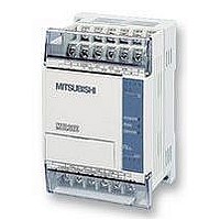
FX1S-30MR-ES/UL MITSUBISHI, FX1S-30MR-ES/UL Datasheet - Page 196

FX1S-30MR-ES/UL
Manufacturer Part Number
FX1S-30MR-ES/UL
Description
PLC, 16 IN, 14 RELAY OUT, 110V/2
Manufacturer
MITSUBISHI
Datasheet
1.FX1S-30MR-ESUL.pdf
(380 pages)
Specifications of FX1S-30MR-ES/UL
No. Of Analogue Inputs
16
No. Of Analogue Outputs
14
Ip/nema Rating
IP10
Approval Bodies
CE, CUL, UL
External Depth
49mm
External Length / Height
90mm
External Width
60mm
Mounting Type
Panel
- Current page: 196 of 380
- Download datasheet (7Mb)
FX Series Programmable Controlers
Points to note:
a) FX
b) Users of FX
c) If the RAMP instruction is interrupted before completion, then the current position within the
d) If the RAMP instruction is operated with a constant scan mode, i.e. D8039 is written to with
The RAMP instruction may also be used with special M flags M8193 and M8194 to mimic the
operation of the SER (FNC 61) and RS (FNC 80) respectively when being programmed on
older versions of programming peripherals. See page 1-5 for more details.
mode of the RAMP instruction by controlling
the state of special auxiliary relay M8026.
When M8026 is OFF, the RAMP instruction will
be in repeat mode. This means when the
current value of D equals S2 the RAM P
instruction will automatically reset and start
again, i.e. the contents of D will be reset to that
of S1 and the device D+1 (the number of
current scans) will reset to ‘0’ (zero). This is
shown in the diagram opposite.
When M8026 is set ON, users will be operating
the RAMP instruction in ‘Hold mode’. This
means once the current value of D equals that
of S2, the RAMP instruction will ‘freeze’ in this
state. This means the M8029 will be set ON for
as long as the instruction remains energized
and the value of D will not reset until the
instruction is re-initialized, i.e. the RAMP
instruction is turned from OFF to ON again.
For these PLC’s the mode is fixed as in the same case as FX PLC’s when M8026 has been
set ON, i.e. HOLD mode.
ramp is ‘frozen’ until the drive signal is re-established. Once the RAMP instruction is re-
driven registers D and D+1 reset and the cycle starts from its beginning again.
the desired scan time (slightly longer than the current scan time) and M8039 is set ON. This
would then allow the number of scans n (used to create the ramp between S1and S2) to be
associated to a time. If 1 scan is equal to the contents of D8039 then the time to complete
the ramp is equal to n
2N
and FX
1N
2NC
and FX
users may set the operation
1S
D8039.
PLC’s cannot change the operating mode of the RAMP instruction.
Applied Instructions 5
5-74
Related parts for FX1S-30MR-ES/UL
Image
Part Number
Description
Manufacturer
Datasheet
Request
R

Part Number:
Description:
MITSUBISHI IGBT MODULES
Manufacturer:
MITSUBISHI
Datasheet:

Part Number:
Description:
MITSUBISHI INTELLIGENT POWER MODULES
Manufacturer:
MITSUBISHI
Datasheet:

Part Number:
Description:
TRANSFER-MOLD TYPE INSULATED TYPE
Manufacturer:
MITSUBISHI
Datasheet:

Part Number:
Description:
Manufacturer:
MITSUBISHI
Datasheet:

Part Number:
Description:
30A intelligent power module for flat-base type
Manufacturer:
MITSUBISHI
Datasheet:

Part Number:
Description:
15A - transistor module for medium power switching use, insulated type
Manufacturer:
MITSUBISHI
Datasheet:

Part Number:
Description:
5A power module for transfer-mold type insulated type
Manufacturer:
MITSUBISHI
Datasheet:

Part Number:
Description:
30A intelligent power module for flat-base type
Manufacturer:
MITSUBISHI
Datasheet:

Part Number:
Description:
TRANSFER-MOLD TYPE INSULATED TYPE
Manufacturer:
MITSUBISHI
Datasheet:

Part Number:
Description:
TRANSFER-MOLD TYPE INSULATED TYPE
Manufacturer:
MITSUBISHI
Datasheet:

Part Number:
Description:
20A - transistor module for medium power switching use, insulated type
Manufacturer:
MITSUBISHI
Datasheet:

Part Number:
Description:
20A - transistor module for medium power switching use, insulated type
Manufacturer:
MITSUBISHI
Datasheet:


