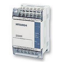
FX1S-30MR-ES/UL MITSUBISHI, FX1S-30MR-ES/UL Datasheet - Page 61

FX1S-30MR-ES/UL
Manufacturer Part Number
FX1S-30MR-ES/UL
Description
PLC, 16 IN, 14 RELAY OUT, 110V/2
Manufacturer
MITSUBISHI
Datasheet
1.FX1S-30MR-ESUL.pdf
(380 pages)
Specifications of FX1S-30MR-ES/UL
No. Of Analogue Inputs
16
No. Of Analogue Outputs
14
Ip/nema Rating
IP10
Approval Bodies
CE, CUL, UL
External Depth
49mm
External Length / Height
90mm
External Width
60mm
Mounting Type
Panel
- Current page: 61 of 380
- Download datasheet (7Mb)
3.5.2
FX Series Programmable Controllers
Single Signal Step Control
Transferring between active STL steps can be controlled by a single signal. There are two
methods the user can program to achieve this result.
Method 1 - Using locking devices
In this example it is necessary to program separate locking devices, and the controlling signal
must only pulse ON. This is to prevent the STL programs from running through.
The example shown below identifies the general program required for this method.
Method 2 - Special Single Pulse Flags
Using the pulse contacts (LDP, LDF, ANP, etc.) and a special range of M devices (M2800 to
M3071) the same result as method 1 can be achieved. The special feature of these devices
prevents run through of the states, as only the first occurrence of the LDP instruction will
activate.
The example program below shows the necessary instructions.
- S30 is activated when M0 is first pulsed ON.
- The operation of M1 prevents the sequence
- After one scan the pulsed M0 and the ‘lock’
- On the next pulse of M0 the STL step will
- The reason for the use of the ‘lock’ devices M1
- Assume S50 is already active.
- When X01 activates M2800, this in turn
- The LDP M2800 instruction in the
- When X01 next activates M2800, the
from continuing because although M0 is ON,
the transfer requirements, need M0 to be ON
and M1 to be OFF.
device M1 are reset.
transfer program control from S31 to the next
step in a similar manner. This time using M2 as
t h e ‘ lo c k ’ d e v i c e b e c a u s e d u a l c o i ls in
successive steps is not allowed.
and M2 is because of the handshaking period
when both states involved in the transfer of
program control are ON for 1 program scan. Without the ‘locks’ it would be possible to
immediately skip through all of the STL states in one go!
activates the LDP M2800 instruction in
S50 and the flow moves on to step
S51.
transition part of S51 does not execute
because this is the second occurrence
of M2800 in a pulse contact.
LDP instruction in S51 is the first
o c c u r r e n c e b e c a u s e S 5 0 i s n o w
inactive. Thus, control passes to the
next step in the same manner.
LAD0
M2800
M2800
S 50
S 51
M2800
M2800
X001
M0
M0
M1
M0
M2
M2800
S 31
S 30
M2800
M2800
STL Programming 3
SET
SET
Do not use the
step control
device in a
pulse contact
within the main
program body.
PLS
PLS
3-9
S51
Snn
M1
M2
Related parts for FX1S-30MR-ES/UL
Image
Part Number
Description
Manufacturer
Datasheet
Request
R

Part Number:
Description:
MITSUBISHI IGBT MODULES
Manufacturer:
MITSUBISHI
Datasheet:

Part Number:
Description:
MITSUBISHI INTELLIGENT POWER MODULES
Manufacturer:
MITSUBISHI
Datasheet:

Part Number:
Description:
TRANSFER-MOLD TYPE INSULATED TYPE
Manufacturer:
MITSUBISHI
Datasheet:

Part Number:
Description:
Manufacturer:
MITSUBISHI
Datasheet:

Part Number:
Description:
30A intelligent power module for flat-base type
Manufacturer:
MITSUBISHI
Datasheet:

Part Number:
Description:
15A - transistor module for medium power switching use, insulated type
Manufacturer:
MITSUBISHI
Datasheet:

Part Number:
Description:
5A power module for transfer-mold type insulated type
Manufacturer:
MITSUBISHI
Datasheet:

Part Number:
Description:
30A intelligent power module for flat-base type
Manufacturer:
MITSUBISHI
Datasheet:

Part Number:
Description:
TRANSFER-MOLD TYPE INSULATED TYPE
Manufacturer:
MITSUBISHI
Datasheet:

Part Number:
Description:
TRANSFER-MOLD TYPE INSULATED TYPE
Manufacturer:
MITSUBISHI
Datasheet:

Part Number:
Description:
20A - transistor module for medium power switching use, insulated type
Manufacturer:
MITSUBISHI
Datasheet:

Part Number:
Description:
20A - transistor module for medium power switching use, insulated type
Manufacturer:
MITSUBISHI
Datasheet:


