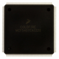
MCF5407CAI220 Freescale Semiconductor, MCF5407CAI220 Datasheet - Page 100

MCF5407CAI220
Manufacturer Part Number
MCF5407CAI220
Description
IC MPU 32B 220MHZ COLDF 208-FQFP
Manufacturer
Freescale Semiconductor
Series
MCF540xr
Specifications of MCF5407CAI220
Core Processor
Coldfire V4
Core Size
32-Bit
Speed
220MHz
Connectivity
EBI/EMI, I²C, UART/USART
Peripherals
DMA, WDT
Number Of I /o
16
Program Memory Type
ROMless
Ram Size
4K x 8
Voltage - Supply (vcc/vdd)
1.65 V ~ 3.6 V
Oscillator Type
External
Operating Temperature
-40°C ~ 85°C
Package / Case
208-FQFP
Processor Series
MCF540x
Core
ColdFire V4
Data Bus Width
32 bit
Program Memory Size
8 KB
Data Ram Size
4 KB
Maximum Clock Frequency
162 MHz
Number Of Programmable I/os
16
Operating Supply Voltage
1.8 V to 3.3 V
Mounting Style
SMD/SMT
3rd Party Development Tools
JLINK-CF-BDM26, EWCF
Cpu Speed
220MHz
Embedded Interface Type
I2C, UART
Digital Ic Case Style
FQFP
No. Of Pins
208
Supply Voltage Range
3.3V
Rohs Compliant
Yes
For Use With
M5407C3 - KIT EVAL FOR MCF5407 W/ETHERNET
Lead Free Status / RoHS Status
Lead free / RoHS Compliant
Eeprom Size
-
Program Memory Size
-
Data Converters
-
Lead Free Status / Rohs Status
Lead free / RoHS Compliant
Available stocks
Company
Part Number
Manufacturer
Quantity
Price
Company:
Part Number:
MCF5407CAI220
Manufacturer:
Freescale
Quantity:
789
Company:
Part Number:
MCF5407CAI220
Manufacturer:
Freescale Semiconductor
Quantity:
10 000
- Current page: 100 of 546
- Download datasheet (7Mb)
Exception Processing Overview
2.8.2 Processor Exceptions
Table 2-22 describes MCF5407 exceptions.
2-34
Access Error
Address
Error
Illegal
Instruction
Divide by
Zero
Privilege
Violation
Trace
Exception
Exception
Access errors are reported only in conjunction with an attempted store to write-protected memory.
Thus, access errors associated with instruction fetch or operand read accesses are not possible.
The Version 4 processor, unlike the Version 2 and 3 processors, updates the condition code register
if a write-protect error occurs during a CLR or MOV3Q operation to memory.
Caused by an attempted execution transferring control to an odd instruction address (that is, if bit 0 of
the target address is set), an attempted use of a word-sized index register (Xi.w) or a scale factor of
8 on an indexed effective addressing mode, or attempted execution of an instruction with a full-format
indexed addressing mode.
If an address error occurs on a JSR instruction, the Version 4 processor first pushes the return
address onto the stack and then calculates the target address. On Version 2 and 3 processors, these
functions are reversed.
If an address error occurs on an RTS instruction, the Version 4 processor preserves the original
return PC and writes the exception stack frame above this value. On Version 2 and 3 processors, the
faulting return PC is overwritten by the address error stack frame.
On Version 2 ColdFire implementations, only some illegal opcodes were decoded and generated an
illegal instruction exception. Version 3 and Version 4 processors decode the full 16-bit opcode and
generate this exception if execution of an unsupported instruction is attempted. Additionally,
attempting to execute an illegal line A or line F opcode generates unique exception types: vectors 10
and 11, respectively.
ColdFire processors do not provide illegal instruction detection on extension words of any instruction,
including MOVEC. Attempting to execute an instruction with an illegal extension word causes
undefined results.
Attempted division by zero causes an exception (vector 5, offset = 0x014) except when the PC points
to the faulting instruction (DIVU, DIVS, REMU, REMS).
Caused by attempted execution of a supervisor mode instruction while in user mode. The ColdFire
Programmer’s Reference Manual lists supervisor- and user-mode instructions.
ColdFire processors provide instruction-by-instruction tracing. While the processor is in trace mode
(SR[T] = 1), instruction completion signals a trace exception. This allows a debugger to monitor
program execution.
The only exception to this definition is the STOP instruction. If the processor is in trace mode, the
instruction before the STOP executes and then generates a trace exception. In the exception stack
frame, the PC points to the STOP opcode. When the trace handler is exited, the STOP instruction is
executed, loading the SR with the immediate operand from the instruction. The processor then
generates a trace exception. The PC in the exception stack frame points to the instruction after
STOP, and the SR reflects the just-loaded value.
If the processor is not in trace mode and executes a STOP instruction where the immediate operand
sets the trace bit in the SR, hardware loads the SR and generates a trace exception. The PC in the
exception stack frame points to the instruction after STOP, and the SR reflects the just-loaded value.
Because ColdFire processors do not support hardware stacking of multiple exceptions, it is the
responsibility of the operating system to check for trace mode after processing other exception types.
As an example, consider a TRAP instruction executing in trace mode. The processor initiates the
TRAP exception and passes control to the corresponding handler. If the system requires that a trace
exception be processed, the TRAP exception handler must check for this condition (SR[15] in the
exception stack frame asserted) and pass control to the trace handler before returning from the
original exception.
Table 2-22. MCF5407 Exceptions
MCF5407 User’s Manual
Description
Related parts for MCF5407CAI220
Image
Part Number
Description
Manufacturer
Datasheet
Request
R
Part Number:
Description:
Mcf5407 Coldfire Integrated Microprocessor User
Manufacturer:
Freescale Semiconductor, Inc
Datasheet:
Part Number:
Description:
Manufacturer:
Freescale Semiconductor, Inc
Datasheet:
Part Number:
Description:
Manufacturer:
Freescale Semiconductor, Inc
Datasheet:
Part Number:
Description:
Manufacturer:
Freescale Semiconductor, Inc
Datasheet:
Part Number:
Description:
Manufacturer:
Freescale Semiconductor, Inc
Datasheet:
Part Number:
Description:
Manufacturer:
Freescale Semiconductor, Inc
Datasheet:
Part Number:
Description:
Manufacturer:
Freescale Semiconductor, Inc
Datasheet:
Part Number:
Description:
Manufacturer:
Freescale Semiconductor, Inc
Datasheet:
Part Number:
Description:
Manufacturer:
Freescale Semiconductor, Inc
Datasheet:
Part Number:
Description:
Manufacturer:
Freescale Semiconductor, Inc
Datasheet:
Part Number:
Description:
Manufacturer:
Freescale Semiconductor, Inc
Datasheet:
Part Number:
Description:
Manufacturer:
Freescale Semiconductor, Inc
Datasheet:
Part Number:
Description:
Manufacturer:
Freescale Semiconductor, Inc
Datasheet:
Part Number:
Description:
Manufacturer:
Freescale Semiconductor, Inc
Datasheet:
Part Number:
Description:
Manufacturer:
Freescale Semiconductor, Inc
Datasheet:


