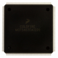
MCF5407CAI220 Freescale Semiconductor, MCF5407CAI220 Datasheet - Page 345

MCF5407CAI220
Manufacturer Part Number
MCF5407CAI220
Description
IC MPU 32B 220MHZ COLDF 208-FQFP
Manufacturer
Freescale Semiconductor
Series
MCF540xr
Specifications of MCF5407CAI220
Core Processor
Coldfire V4
Core Size
32-Bit
Speed
220MHz
Connectivity
EBI/EMI, I²C, UART/USART
Peripherals
DMA, WDT
Number Of I /o
16
Program Memory Type
ROMless
Ram Size
4K x 8
Voltage - Supply (vcc/vdd)
1.65 V ~ 3.6 V
Oscillator Type
External
Operating Temperature
-40°C ~ 85°C
Package / Case
208-FQFP
Processor Series
MCF540x
Core
ColdFire V4
Data Bus Width
32 bit
Program Memory Size
8 KB
Data Ram Size
4 KB
Maximum Clock Frequency
162 MHz
Number Of Programmable I/os
16
Operating Supply Voltage
1.8 V to 3.3 V
Mounting Style
SMD/SMT
3rd Party Development Tools
JLINK-CF-BDM26, EWCF
Cpu Speed
220MHz
Embedded Interface Type
I2C, UART
Digital Ic Case Style
FQFP
No. Of Pins
208
Supply Voltage Range
3.3V
Rohs Compliant
Yes
For Use With
M5407C3 - KIT EVAL FOR MCF5407 W/ETHERNET
Lead Free Status / RoHS Status
Lead free / RoHS Compliant
Eeprom Size
-
Program Memory Size
-
Data Converters
-
Lead Free Status / Rohs Status
Lead free / RoHS Compliant
Available stocks
Company
Part Number
Manufacturer
Quantity
Price
Company:
Part Number:
MCF5407CAI220
Manufacturer:
Freescale
Quantity:
789
Company:
Part Number:
MCF5407CAI220
Manufacturer:
Freescale Semiconductor
Quantity:
10 000
- Current page: 345 of 546
- Download datasheet (7Mb)
UART1 has the following additional features:
14.3 Register Descriptions
This section contains a detailed description of each register and its specific function.
Flowcharts in Section 14.5.6, “Programming,” describe basic UART module programming.
The operation of the UART module is controlled by writing control bytes into the
appropriate registers. Table 14-1 is a memory map for UART module registers.
• Each channel programmable to normal (full-duplex), automatic echo, local
• Automatic wake-up mode for multidrop applications
• Four maskable interrupt conditions
• UART0 and UART1 have interrupt capability to DMA channels 2 and 3,
• Parity, framing, and overrun error detection
• False-start bit detection
• Line-break detection and generation
• Detection of breaks originating in the middle of a character
• Start/end break interrupt/status
• Programmable to interface to an 8- or 16-bit CODEC for soft modem support
• Programmable to function as a digital AC ’97 controller
• Tx and Rx FIFOs can hold the following:
• Both DMA channels associated with the UARTs can be programmed to service
• No parity error, framing error, or line break detection in modem mode
loop-back, or remote loop-back mode
respectively, when either the RxRDY or FFULL bit is set in the USR.
— 32 1-byte samples when programmed as a UART or as an 8-bit CODEC interface
— 16 2-byte samples when programmed as a 16-bit CODEC interface
— 16 20-bit samples when programmed as a digital AC ’97 controller
UART1 (one for the Tx channel and one for the Rx channel)
Chapter 14. UART Modules
Register Descriptions
14-3
Related parts for MCF5407CAI220
Image
Part Number
Description
Manufacturer
Datasheet
Request
R
Part Number:
Description:
Mcf5407 Coldfire Integrated Microprocessor User
Manufacturer:
Freescale Semiconductor, Inc
Datasheet:
Part Number:
Description:
Manufacturer:
Freescale Semiconductor, Inc
Datasheet:
Part Number:
Description:
Manufacturer:
Freescale Semiconductor, Inc
Datasheet:
Part Number:
Description:
Manufacturer:
Freescale Semiconductor, Inc
Datasheet:
Part Number:
Description:
Manufacturer:
Freescale Semiconductor, Inc
Datasheet:
Part Number:
Description:
Manufacturer:
Freescale Semiconductor, Inc
Datasheet:
Part Number:
Description:
Manufacturer:
Freescale Semiconductor, Inc
Datasheet:
Part Number:
Description:
Manufacturer:
Freescale Semiconductor, Inc
Datasheet:
Part Number:
Description:
Manufacturer:
Freescale Semiconductor, Inc
Datasheet:
Part Number:
Description:
Manufacturer:
Freescale Semiconductor, Inc
Datasheet:
Part Number:
Description:
Manufacturer:
Freescale Semiconductor, Inc
Datasheet:
Part Number:
Description:
Manufacturer:
Freescale Semiconductor, Inc
Datasheet:
Part Number:
Description:
Manufacturer:
Freescale Semiconductor, Inc
Datasheet:
Part Number:
Description:
Manufacturer:
Freescale Semiconductor, Inc
Datasheet:
Part Number:
Description:
Manufacturer:
Freescale Semiconductor, Inc
Datasheet:


