MCF5407CAI220 Freescale Semiconductor, MCF5407CAI220 Datasheet - Page 247
MCF5407CAI220
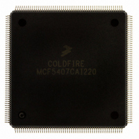
Manufacturer Part Number
MCF5407CAI220
Description
IC MPU 32B 220MHZ COLDF 208-FQFP
Manufacturer
Freescale Semiconductor
Series
MCF540xr
Specifications of MCF5407CAI220
Core Processor
Coldfire V4
Core Size
32-Bit
Speed
220MHz
Connectivity
EBI/EMI, I²C, UART/USART
Peripherals
DMA, WDT
Number Of I /o
16
Program Memory Type
ROMless
Ram Size
4K x 8
Voltage - Supply (vcc/vdd)
1.65 V ~ 3.6 V
Oscillator Type
External
Operating Temperature
-40°C ~ 85°C
Package / Case
208-FQFP
Processor Series
MCF540x
Core
ColdFire V4
Data Bus Width
32 bit
Program Memory Size
8 KB
Data Ram Size
4 KB
Maximum Clock Frequency
162 MHz
Number Of Programmable I/os
16
Operating Supply Voltage
1.8 V to 3.3 V
Mounting Style
SMD/SMT
3rd Party Development Tools
JLINK-CF-BDM26, EWCF
Cpu Speed
220MHz
Embedded Interface Type
I2C, UART
Digital Ic Case Style
FQFP
No. Of Pins
208
Supply Voltage Range
3.3V
Rohs Compliant
Yes
For Use With
M5407C3 - KIT EVAL FOR MCF5407 W/ETHERNET
Lead Free Status / RoHS Status
Lead free / RoHS Compliant
Eeprom Size
-
Program Memory Size
-
Data Converters
-
Lead Free Status / Rohs Status
Lead free / RoHS Compliant
Available stocks
Company
Part Number
Manufacturer
Quantity
Price
Company:

Part Number:
MCF5407CAI220
Manufacturer:
Freescale
Quantity:
789
Company:
Part Number:
MCF5407CAI220
Manufacturer:
Freescale Semiconductor
Quantity:
10 000


The free time between a STOP and the next START condition is built into the hardware that
generates the START cycle. Depending on the relative frequencies of the system clock and
the SCL period, it may be necessary to wait until the I
address to the I2DR before proceeding with the following instructions.
The following example signals START and transmits the first byte of data (slave address):
CHFLAG
TXSTART MOVE.B I2CR,-(A0);Set transmit mode
IFREE
8.6.3 Post-Transfer Software Response
Sending or receiving a byte sets the I2SR[ICF], which indicates one byte communication
is finished. I2SR[IIF] is also set. An interrupt is generated if the interrupt function is
enabled during initialization by setting I2CR[IIEN]. Software must first clear IIF in the
interrupt routine. ICF is cleared either by reading from I2DR in receive mode or by writing
to I2DR in transmit mode.
Software can service the I
function is disabled. Polling should monitor IIF rather than ICF because that operation is
different when arbitration is lost.
When an interrupt occurs at the end of the address cycle, the master is always in transmit
mode; that is, the address is sent. If master receive mode is required (I2DR[R/W],
I2CR[MTX] should be toggled.
During slave-mode address cycles (I2SR[IAAS] = 1), I2SR[SRW] is read to determine the
direction of the next transfer. MTX is programmed accordingly. For slave-mode data cycles
(IAAS = 0), SRW is invalid. MTX should be read to determine the current transfer
direction.
The following is an example of a software response by a master transmitter in the interrupt
routine (see Figure 8-10).
I2SR
MOVE.B I2SR,-(A0);Check I2SR[MBB]
BTST.B #5, (A0)+
BNE.S CHFLAG;If I2SR[MBB] = 1, wait until it is clear
BSET.B #4,(A0)
MOVE.B (A0)+, I2CR
MOVE.B I2CR, -(A0);Set master mode
BSET.B #5, (A0);Generate START condition
MOVE.B (A0)+, I2CR
MOVE.B CALLING,-(A0);Transmit the calling address, D0=R/W
MOVE.B (A0)+, I2DR
MOVE.B I2SR,-(A0);Check I2SR[MBB]
BTST.B #5, (A0)+;
BEQ.S IFREE;
LEA.L I2SR,-(A7);Load effective address
BCLR.B #1,(A7)+;Clear the IIF flag
MOVE.B I2CR,-(A7);Push the address on stack,
BTST.B #5,(A7)+;check the MSTA flag
BEQ.S SLAVE;Branch if slave mode
MOVE.B I2CR,-(A7);Push the address on stack
BTST.B #4,(A7)+;check the mode flag
;If it is clear, wait until it is set.
2
C I/O in the main program by monitoring IIF if the interrupt
Chapter 8. I
2
C Module
2
C is busy after writing the calling
I
2
C Programming Examples
8-11
Related parts for MCF5407CAI220
Image
Part Number
Description
Manufacturer
Datasheet
Request
R

Part Number:
Description:
Mcf5407 Coldfire Integrated Microprocessor User
Manufacturer:
Freescale Semiconductor, Inc
Datasheet:
Part Number:
Description:
Manufacturer:
Freescale Semiconductor, Inc
Datasheet:
Part Number:
Description:
Manufacturer:
Freescale Semiconductor, Inc
Datasheet:
Part Number:
Description:
Manufacturer:
Freescale Semiconductor, Inc
Datasheet:
Part Number:
Description:
Manufacturer:
Freescale Semiconductor, Inc
Datasheet:
Part Number:
Description:
Manufacturer:
Freescale Semiconductor, Inc
Datasheet:
Part Number:
Description:
Manufacturer:
Freescale Semiconductor, Inc
Datasheet:
Part Number:
Description:
Manufacturer:
Freescale Semiconductor, Inc
Datasheet:
Part Number:
Description:
Manufacturer:
Freescale Semiconductor, Inc
Datasheet:
Part Number:
Description:
Manufacturer:
Freescale Semiconductor, Inc
Datasheet:
Part Number:
Description:
Manufacturer:
Freescale Semiconductor, Inc
Datasheet:
Part Number:
Description:
Manufacturer:
Freescale Semiconductor, Inc
Datasheet:
Part Number:
Description:
Manufacturer:
Freescale Semiconductor, Inc
Datasheet:
Part Number:
Description:
Manufacturer:
Freescale Semiconductor, Inc
Datasheet:
Part Number:
Description:
Manufacturer:
Freescale Semiconductor, Inc
Datasheet: