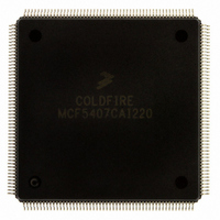
MCF5407CAI220 Freescale Semiconductor, MCF5407CAI220 Datasheet - Page 33

MCF5407CAI220
Manufacturer Part Number
MCF5407CAI220
Description
IC MPU 32B 220MHZ COLDF 208-FQFP
Manufacturer
Freescale Semiconductor
Series
MCF540xr
Specifications of MCF5407CAI220
Core Processor
Coldfire V4
Core Size
32-Bit
Speed
220MHz
Connectivity
EBI/EMI, I²C, UART/USART
Peripherals
DMA, WDT
Number Of I /o
16
Program Memory Type
ROMless
Ram Size
4K x 8
Voltage - Supply (vcc/vdd)
1.65 V ~ 3.6 V
Oscillator Type
External
Operating Temperature
-40°C ~ 85°C
Package / Case
208-FQFP
Processor Series
MCF540x
Core
ColdFire V4
Data Bus Width
32 bit
Program Memory Size
8 KB
Data Ram Size
4 KB
Maximum Clock Frequency
162 MHz
Number Of Programmable I/os
16
Operating Supply Voltage
1.8 V to 3.3 V
Mounting Style
SMD/SMT
3rd Party Development Tools
JLINK-CF-BDM26, EWCF
Cpu Speed
220MHz
Embedded Interface Type
I2C, UART
Digital Ic Case Style
FQFP
No. Of Pins
208
Supply Voltage Range
3.3V
Rohs Compliant
Yes
For Use With
M5407C3 - KIT EVAL FOR MCF5407 W/ETHERNET
Lead Free Status / RoHS Status
Lead free / RoHS Compliant
Eeprom Size
-
Program Memory Size
-
Data Converters
-
Lead Free Status / Rohs Status
Lead free / RoHS Compliant
Available stocks
Company
Part Number
Manufacturer
Quantity
Price
Company:
Part Number:
MCF5407CAI220
Manufacturer:
Freescale
Quantity:
789
Company:
Part Number:
MCF5407CAI220
Manufacturer:
Freescale Semiconductor
Quantity:
10 000
- Current page: 33 of 546
- Download datasheet (7Mb)
Table
Number
15-3
16-1
16-2
16-3
16-4
16-5
17-1
17-2
17-3
17-4
17-5
17-6
17-7
17-8
17-9
17-10
17-11
17-12
17-13
17-14
17-15
18-1
18-2
18-3
18-4
18-5
18-6
18-7
18-8
18-9
18-10
18-11
18-12
19-1
19-2
19-3
19-4
20-1
20-2
20-3
20-4
20-5
20-6
Relationship between PADAT Register and Parallel Port Pin (PP) ........................... 15-3
Pins 1–52 (Left, Top-to-Bottom) ................................................................................ 16-1
Pins 53–104 (Bottom, Left-to-Right).......................................................................... 16-3
Pins 105–156 (Right, Bottom-to-Top)........................................................................ 16-5
Pins 157–208 (Top, Right-to-Left) ............................................................................. 16-6
Dimensions ............................................................................................................... 16-11
MCF5407 Signal Index............................................................................................... 17-3
MCF5407 Alphabetical Signal Index ......................................................................... 17-5
Data Pin Configuration ............................................................................................... 17-8
Bus Cycle Size Encoding............................................................................................ 17-9
Bus Cycle Transfer Type Encoding.......................................................................... 17-10
TM[2:0] Encodings for TT = 00 (Normal Access)................................................... 17-10
TM2 Encoding for DMA as Master (TT = 01) ......................................................... 17-11
TM[1:0] Encoding for DMA as Master (TT = 01) ................................................... 17-11
TM[2:0] Encodings for TT = 10 (Emulator Access) ................................................ 17-11
TM[2:0] Encodings for TT = 11 (Interrupt Level) ................................................... 17-12
Data Pin Configuration ............................................................................................. 17-14
D7 Selection of CS0 Automatic Acknowledge ........................................................ 17-14
D6 and D5 Selection of CS0 Port Size ..................................................................... 17-14
D3/BE_CONFIG, BE[3:0] Boot Configuration ....................................................... 17-15
D4/ADDR_CONFIG, Address Pin Assignment....................................................... 17-15
ColdFire Bus Signal Summary ................................................................................... 18-1
Bus Cycle Size Encoding............................................................................................ 18-3
Accesses by Matches in CSCRs and DACRs ............................................................. 18-5
Bus Cycle States ......................................................................................................... 18-6
Allowable Line Access Patterns ............................................................................... 18-12
MCF5407 Arbitration Protocol States ...................................................................... 18-20
ColdFire Bus Arbitration Signal Summary............................................................... 18-21
Cycles for Basic No-Wait-State External Master Access......................................... 18-23
Cycles for External Master Burst Line Access to 32-Bit Port .................................. 18-24
MCF5407 Two-Wire Bus Arbitration Protocol Transition Conditions.................... 18-28
Three-Wire Bus Arbitration Protocol Transition Conditions ................................... 18-32
Data Pin Configuration ............................................................................................. 18-35
JTAG Pin Descriptions ............................................................................................... 19-3
JTAG Instructions....................................................................................................... 19-5
IDCODE Bit Assignments.......................................................................................... 19-6
Boundary-Scan Bit Definitions................................................................................... 19-7
Absolute Maximum Ratings ....................................................................................... 20-1
Operating Temperatures.............................................................................................. 20-1
DC Electrical Specifications ....................................................................................... 20-2
Divide Ratio Encodings .............................................................................................. 20-4
Clock Timing Specification ........................................................................................ 20-5
Input AC Timing Specification................................................................................... 20-6
TABLES
Tables
Title
Number
Page
xxxiii
Related parts for MCF5407CAI220
Image
Part Number
Description
Manufacturer
Datasheet
Request
R
Part Number:
Description:
Mcf5407 Coldfire Integrated Microprocessor User
Manufacturer:
Freescale Semiconductor, Inc
Datasheet:
Part Number:
Description:
Manufacturer:
Freescale Semiconductor, Inc
Datasheet:
Part Number:
Description:
Manufacturer:
Freescale Semiconductor, Inc
Datasheet:
Part Number:
Description:
Manufacturer:
Freescale Semiconductor, Inc
Datasheet:
Part Number:
Description:
Manufacturer:
Freescale Semiconductor, Inc
Datasheet:
Part Number:
Description:
Manufacturer:
Freescale Semiconductor, Inc
Datasheet:
Part Number:
Description:
Manufacturer:
Freescale Semiconductor, Inc
Datasheet:
Part Number:
Description:
Manufacturer:
Freescale Semiconductor, Inc
Datasheet:
Part Number:
Description:
Manufacturer:
Freescale Semiconductor, Inc
Datasheet:
Part Number:
Description:
Manufacturer:
Freescale Semiconductor, Inc
Datasheet:
Part Number:
Description:
Manufacturer:
Freescale Semiconductor, Inc
Datasheet:
Part Number:
Description:
Manufacturer:
Freescale Semiconductor, Inc
Datasheet:
Part Number:
Description:
Manufacturer:
Freescale Semiconductor, Inc
Datasheet:
Part Number:
Description:
Manufacturer:
Freescale Semiconductor, Inc
Datasheet:
Part Number:
Description:
Manufacturer:
Freescale Semiconductor, Inc
Datasheet:


