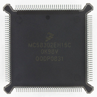
MC68302EH16C Freescale Semiconductor, MC68302EH16C Datasheet - Page 140

MC68302EH16C
Manufacturer Part Number
MC68302EH16C
Description
IC MPU MULTI-PROTOCOL 132-PQFP
Manufacturer
Freescale Semiconductor
Datasheets
1.MC68302AG20C.pdf
(4 pages)
2.MC68302AG20C.pdf
(2 pages)
3.MC68302AG20C.pdf
(13 pages)
4.MC68302EH16C.pdf
(481 pages)
Specifications of MC68302EH16C
Processor Type
M683xx 32-Bit
Speed
16MHz
Voltage
5V
Mounting Type
Surface Mount
Package / Case
132-MQFP, 132-PQFP
Controller Family/series
68K
Core Size
32 Bit
Ram Memory Size
1152Byte
Cpu Speed
16MHz
No. Of Timers
3
Embedded Interface Type
SCP, TDM
Digital Ic Case Style
PQFP
Rohs Compliant
Yes
Family Name
M68000
Device Core
ColdFire
Device Core Size
32b
Frequency (max)
16MHz
Instruction Set Architecture
RISC
Supply Voltage 1 (typ)
5V
Operating Temp Range
0C to 70C
Operating Temperature Classification
Commercial
Mounting
Surface Mount
Pin Count
132
Package Type
PQFP
Lead Free Status / RoHS Status
Lead free / RoHS Compliant
Features
-
Lead Free Status / Rohs Status
RoHS Compliant part
Electrostatic Device
Available stocks
Company
Part Number
Manufacturer
Quantity
Price
Company:
Part Number:
MC68302EH16C
Manufacturer:
Freescale Semiconductor
Quantity:
135
Company:
Part Number:
MC68302EH16C
Manufacturer:
PANA
Quantity:
99
Company:
Part Number:
MC68302EH16C
Manufacturer:
Freescale Semiconductor
Quantity:
10 000
Part Number:
MC68302EH16C
Manufacturer:
FREESCALE
Quantity:
20 000
Company:
Part Number:
MC68302EH16CB1
Manufacturer:
Freescale Semiconductor
Quantity:
10 000
Company:
Part Number:
MC68302EH16CR2
Manufacturer:
Freescale Semiconductor
Quantity:
10 000
- MC68302AG20C PDF datasheet
- MC68302AG20C PDF datasheet #2
- MC68302AG20C PDF datasheet #3
- MC68302EH16C PDF datasheet #4
- Current page: 140 of 481
- Download datasheet (2Mb)
Communications Processor (CP)
NMSI mode. The SIMODE register is a memory-mapped read-write register cleared by re-
set.
SETZ—Set L1TXD to zero (valid only for the GCI interface)
SYNC/SCIT—SYNC Mode/SCIT Select Support
SDIAG1–SDIAG0—Serial Interface Diagnostic Mode (NMSI1 Pins Only)
4-20
SYNC is valid only in PCM mode.
The SCIT (Special Circuit Interface T) interface mode is valid only in GCI mode.
B1RB
SETZ
0 = Normal operation
1 = L1TXD output set to a logic zero (used in GCI activation, refer to 4.4.2 GCI Inter-
0 = One pulse wide prior to the 8-bit data
1 = N pulses wide and envelopes the N-bit data
0 = SCIT support disabled
1 = SCIT D-channel collision enabled. Bit 4 of channel 2 C/I used by the IMP for receiv-
00 = Normal operation
01 = Automatic echo
10 = Internal loopback
11 = Loopback control
15
7
face)
ing indication on the availability of the S interface D channel.
The channel automatically retransmits the received data on a bit-by-bit basis. The
receiver operates normally, but the transmitter can only retransmit received data.
In this mode, L1GR is ignored.
The transmitter output (L1TXD) is internally connected to the receiver input
(L1RXD). The receiver and the transmitter operate normally. Transmitted data ap-
pears on the L1TXD pin, and any external data received on L1RXD pin is ignored.
In this mode, L1RQ is asserted normally, and L1GR is ignored.
In this mode, the transmitter output (TXD1/L1TXD) is internally connected to the
receiver input (RXD1/L1RXD). The TXD1/L1TXD, TXD2, TXD3, RTS1, RTS2,
and RTS3 pins will be high, but L1TXD will be three-stated in IDL and PCM
modes. This mode may be used to accomplish multiplex mode loopback testing
without affecting the multiplexed layer 1 interface. It also prevents an SCC's indi-
vidual loopback (configured in the SCM) from affecting the pins of its associated
NMSI interface.
SYNC/SCIT
B1RA
14
6
SDIAG1
DRB
13
5
MC68302 USER’S MANUAL
SDIAG0
DRA
12
4
SDC2
MSC3
11
3
MSC2
SDC1
10
2
B2RB
MS1
9
1
MOTOROLA
B2RA
MS0
8
0
Related parts for MC68302EH16C
Image
Part Number
Description
Manufacturer
Datasheet
Request
R
Part Number:
Description:
Manufacturer:
Freescale Semiconductor, Inc
Datasheet:

Part Number:
Description:
MC68302 Configuring the Chip Selects on the MC68302
Manufacturer:
Motorola / Freescale Semiconductor

Part Number:
Description:
MC68302 Design Concept - Expanding Interrupts on the MC68302
Manufacturer:
Motorola / Freescale Semiconductor

Part Number:
Description:
MC68302 MC68302 Adapting a WAN Controller to a LAN Environment
Manufacturer:
Motorola / Freescale Semiconductor

Part Number:
Description:
MC68302 EKB Applications - Power Measurements on the MC68302
Manufacturer:
Motorola / Freescale Semiconductor

Part Number:
Description:
MC68302 Interfacing the MC68020 to a Slave MC68302
Manufacturer:
Motorola / Freescale Semiconductor

Part Number:
Description:
MC68302 MC68302 Software Performance
Manufacturer:
Motorola / Freescale Semiconductor

Part Number:
Description:
MC68302 Evaluating EDX on the ADS302
Manufacturer:
Motorola / Freescale Semiconductor

Part Number:
Description:
MC68302 Design Advisory #1 - MC68SC302 Passive ISDN Protocol Engine
Manufacturer:
Motorola / Freescale Semiconductor

Part Number:
Description:
MC68302, MC68360, and MPC860 Characteristics and Design Notes for Crystal Feedback Oscillators
Manufacturer:
Motorola / Freescale Semiconductor
Part Number:
Description:
Mc68302 Integrated Multi-protocol Processor
Manufacturer:
Freescale Semiconductor, Inc
Datasheet:
Part Number:
Description:
Manufacturer:
Freescale Semiconductor, Inc
Datasheet:
Part Number:
Description:
Manufacturer:
Freescale Semiconductor, Inc
Datasheet:
Part Number:
Description:
Manufacturer:
Freescale Semiconductor, Inc
Datasheet:
Part Number:
Description:
Manufacturer:
Freescale Semiconductor, Inc
Datasheet:


