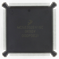
MC68302EH16C Freescale Semiconductor, MC68302EH16C Datasheet - Page 466

MC68302EH16C
Manufacturer Part Number
MC68302EH16C
Description
IC MPU MULTI-PROTOCOL 132-PQFP
Manufacturer
Freescale Semiconductor
Datasheets
1.MC68302AG20C.pdf
(4 pages)
2.MC68302AG20C.pdf
(2 pages)
3.MC68302AG20C.pdf
(13 pages)
4.MC68302EH16C.pdf
(481 pages)
Specifications of MC68302EH16C
Processor Type
M683xx 32-Bit
Speed
16MHz
Voltage
5V
Mounting Type
Surface Mount
Package / Case
132-MQFP, 132-PQFP
Controller Family/series
68K
Core Size
32 Bit
Ram Memory Size
1152Byte
Cpu Speed
16MHz
No. Of Timers
3
Embedded Interface Type
SCP, TDM
Digital Ic Case Style
PQFP
Rohs Compliant
Yes
Family Name
M68000
Device Core
ColdFire
Device Core Size
32b
Frequency (max)
16MHz
Instruction Set Architecture
RISC
Supply Voltage 1 (typ)
5V
Operating Temp Range
0C to 70C
Operating Temperature Classification
Commercial
Mounting
Surface Mount
Pin Count
132
Package Type
PQFP
Lead Free Status / RoHS Status
Lead free / RoHS Compliant
Features
-
Lead Free Status / Rohs Status
RoHS Compliant part
Electrostatic Device
Available stocks
Company
Part Number
Manufacturer
Quantity
Price
Company:
Part Number:
MC68302EH16C
Manufacturer:
Freescale Semiconductor
Quantity:
135
Company:
Part Number:
MC68302EH16C
Manufacturer:
PANA
Quantity:
99
Company:
Part Number:
MC68302EH16C
Manufacturer:
Freescale Semiconductor
Quantity:
10 000
Part Number:
MC68302EH16C
Manufacturer:
FREESCALE
Quantity:
20 000
Company:
Part Number:
MC68302EH16CB1
Manufacturer:
Freescale Semiconductor
Quantity:
10 000
Company:
Part Number:
MC68302EH16CR2
Manufacturer:
Freescale Semiconductor
Quantity:
10 000
- MC68302AG20C PDF datasheet
- MC68302AG20C PDF datasheet #2
- MC68302AG20C PDF datasheet #3
- MC68302EH16C PDF datasheet #4
- Current page: 466 of 481
- Download datasheet (2Mb)
Design Checklist
F-2
9. Chip Select, DTAC K Generation
10. Chip Select, Option Register
11. A0–A7, D0–D7, Initialize, Reset
12. BSET Instruction, Byte
13. Exception Vector Table, Initialize, Reset
14. Stack Pointer, Initialize, Reset
15. Parameter RAM, Initialize, Reset
16. EQU, Parameter RAM
spec (see spec 32), or the total system reset may not be terminated correctly and un-
usual behavior may occur. Also, when using the RESET instruction to reset the
MC68302 internal peripherals, a strong pullup (such as 1.2K ohms) may be required
for proper rise times.
If unexpected behavior is occurring on the DTACK line, such as early or late assertion
or negation, then often the problem is traced to another component on the board that
is generating DTACK at the same time as the IMP DTACK generator. An often over-
looked source for DTACK generation is the emulator overlay memory (if an emulator
is used), which may have been inadvertently configured to overlap with a chip-select
area of the IMP. Very unusual behavior can result, especially if the number of wait
states programmed for the chip select is different from that of the overlay memory.
When setting up the chip select option register to operate as an address mask, the val-
ue programmed into the base address mask field should normally have all ones at the
left end and all zeros at the right end. Any zeros mixed between ones in the option reg-
ister base address mask field will cause multiple responses of the chip-select pin
throughout the MC68302 address space. In most applications, this is undesirable and
confusing.
The M68000 registers A0–A7 and D0–D7 do not have predefined values upon a total
system reset. The use of uninitialized (or partially uninitialized) registers can cause in-
termittent and erratic software behavior since the initialized register values may vary
from reset to reset.
To use the bit set instruction (BSET) to set a bit in the lower half of a word-sized reg-
ister or memory location, one MUST perform a byte operation on the byte address, i.e.,
word_address + 1. For example, to set bit zero of a word address $3000, one must
issue BSET.B #0,#$3001. There is no BSET.W instruction available in the MC68000.
This also applies to the BTST instruction.
Failure to provide the M68000 core exception vector table with vectors can cause er-
ratic behavior when an exception (such as bus error) occurs. Make sure that the boot
ROM/EPROM has exception vectors initialized, and that the initial reset vector causes
the program to start at an address above the vector table.
The stack pointer must be initialized to an EVEN address; otherwise, address errors
will occur when the stack is first used.
To use SCCs with specific protocols, both general-purpose parameters and protocol-
specific parameters must be initialized. Failure to initialize the parameter RAM will re-
sult in erratic behavior since the parameter RAM does not have predefined values
upon a total system reset.
Very unusual problems with the SCCs are often traced to the fact that the source code
MC68360 USER’S MANUAL
MOTOROLA
Related parts for MC68302EH16C
Image
Part Number
Description
Manufacturer
Datasheet
Request
R
Part Number:
Description:
Manufacturer:
Freescale Semiconductor, Inc
Datasheet:

Part Number:
Description:
MC68302 Configuring the Chip Selects on the MC68302
Manufacturer:
Motorola / Freescale Semiconductor

Part Number:
Description:
MC68302 Design Concept - Expanding Interrupts on the MC68302
Manufacturer:
Motorola / Freescale Semiconductor

Part Number:
Description:
MC68302 MC68302 Adapting a WAN Controller to a LAN Environment
Manufacturer:
Motorola / Freescale Semiconductor

Part Number:
Description:
MC68302 EKB Applications - Power Measurements on the MC68302
Manufacturer:
Motorola / Freescale Semiconductor

Part Number:
Description:
MC68302 Interfacing the MC68020 to a Slave MC68302
Manufacturer:
Motorola / Freescale Semiconductor

Part Number:
Description:
MC68302 MC68302 Software Performance
Manufacturer:
Motorola / Freescale Semiconductor

Part Number:
Description:
MC68302 Evaluating EDX on the ADS302
Manufacturer:
Motorola / Freescale Semiconductor

Part Number:
Description:
MC68302 Design Advisory #1 - MC68SC302 Passive ISDN Protocol Engine
Manufacturer:
Motorola / Freescale Semiconductor

Part Number:
Description:
MC68302, MC68360, and MPC860 Characteristics and Design Notes for Crystal Feedback Oscillators
Manufacturer:
Motorola / Freescale Semiconductor
Part Number:
Description:
Mc68302 Integrated Multi-protocol Processor
Manufacturer:
Freescale Semiconductor, Inc
Datasheet:
Part Number:
Description:
Manufacturer:
Freescale Semiconductor, Inc
Datasheet:
Part Number:
Description:
Manufacturer:
Freescale Semiconductor, Inc
Datasheet:
Part Number:
Description:
Manufacturer:
Freescale Semiconductor, Inc
Datasheet:
Part Number:
Description:
Manufacturer:
Freescale Semiconductor, Inc
Datasheet:


