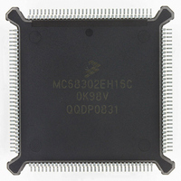
MC68302EH16C Freescale Semiconductor, MC68302EH16C Datasheet - Page 57

MC68302EH16C
Manufacturer Part Number
MC68302EH16C
Description
IC MPU MULTI-PROTOCOL 132-PQFP
Manufacturer
Freescale Semiconductor
Datasheets
1.MC68302AG20C.pdf
(4 pages)
2.MC68302AG20C.pdf
(2 pages)
3.MC68302AG20C.pdf
(13 pages)
4.MC68302EH16C.pdf
(481 pages)
Specifications of MC68302EH16C
Processor Type
M683xx 32-Bit
Speed
16MHz
Voltage
5V
Mounting Type
Surface Mount
Package / Case
132-MQFP, 132-PQFP
Controller Family/series
68K
Core Size
32 Bit
Ram Memory Size
1152Byte
Cpu Speed
16MHz
No. Of Timers
3
Embedded Interface Type
SCP, TDM
Digital Ic Case Style
PQFP
Rohs Compliant
Yes
Family Name
M68000
Device Core
ColdFire
Device Core Size
32b
Frequency (max)
16MHz
Instruction Set Architecture
RISC
Supply Voltage 1 (typ)
5V
Operating Temp Range
0C to 70C
Operating Temperature Classification
Commercial
Mounting
Surface Mount
Pin Count
132
Package Type
PQFP
Lead Free Status / RoHS Status
Lead free / RoHS Compliant
Features
-
Lead Free Status / Rohs Status
RoHS Compliant part
Electrostatic Device
Available stocks
Company
Part Number
Manufacturer
Quantity
Price
Company:
Part Number:
MC68302EH16C
Manufacturer:
Freescale Semiconductor
Quantity:
135
Company:
Part Number:
MC68302EH16C
Manufacturer:
PANA
Quantity:
99
Company:
Part Number:
MC68302EH16C
Manufacturer:
Freescale Semiconductor
Quantity:
10 000
Part Number:
MC68302EH16C
Manufacturer:
FREESCALE
Quantity:
20 000
Company:
Part Number:
MC68302EH16CB1
Manufacturer:
Freescale Semiconductor
Quantity:
10 000
Company:
Part Number:
MC68302EH16CR2
Manufacturer:
Freescale Semiconductor
Quantity:
10 000
- MC68302AG20C PDF datasheet
- MC68302AG20C PDF datasheet #2
- MC68302AG20C PDF datasheet #3
- MC68302EH16C PDF datasheet #4
- Current page: 57 of 481
- Download datasheet (2Mb)
The DAPR contains 24 (A23–A0) address bits of the destination operand used by the IDMA
to access memory or memory-mapped peripheral controller registers. During the IDMA write
cycle, the address on the master address bus is driven from this register. The DAPR may
be programmed by the DAPI bit to be incremented or remain constant after each operand
transfer.
The register is incremented using unsigned arithmetic and will roll over if overflow occurs.
For example, if a register contains $00FFFFFF and is incremented by one, it will roll over to
$00000000. This register can be incremented by one or two depending on the DSIZE bit and
the starting address.
3.1.2.4 Function Code Register (FCR)
The FCR is an 8-bit register.
The SFC and the DFC bits define the source and destination function code values that are
output by the IDMA and the appropriate address registers during an IDMA bus cycle. The
address space on the function code lines may be used by an external memory management
unit (MMU) or other memory-protection device to translate the IDMA logical addresses to
proper physical addresses. The function code value programmed into the FCR is placed on
pins FC2–FC0 during a bus cycle to further qualify the address bus value.
3.1.2.5 Byte Count Register (BCR)
This 16-bit register specifies the amount of data to be transferred by the IDMA; up to 64K
bytes (BCR = 0) is permitted. This register is decremented once for each byte transferred
successfully. BCR may be even or odd as desired. DMA activity will terminate as soon as
this register reaches zero. Thus, an odd number of bytes may be transferred in a 16-bit op-
erand scenario.
3.1.2.6 Channel Status Register (CSR)
The CSR is an 8-bit register used to report events recognized by the IDMA controller. On
recognition of an event, the IDMA sets its corresponding bit in the CSR (regardless of the
INTE and INTN bits in the CMR). The CSR is a memory-mapped register which may be read
at any time. A bit is cleared by writing a one and is left unchanged by writing a zero. More
than one bit may be cleared at a time, and the register is cleared at reset.
Bits 7–4—These bits are reserved for future use.
MOTOROLA
This register is undefined following power-on reset. The user
should always initialize it and should not use the function code
value “111” in this register.
7
1
7
RESERVED
6
MC68302 USER’S MANUAL
DFC
NOTE
4
4
DNS
1
3
3
BES
2
2
SFC
BED
1
System Integration Block (SIB)
DONE
0
0
3-7
Related parts for MC68302EH16C
Image
Part Number
Description
Manufacturer
Datasheet
Request
R
Part Number:
Description:
Manufacturer:
Freescale Semiconductor, Inc
Datasheet:

Part Number:
Description:
MC68302 Configuring the Chip Selects on the MC68302
Manufacturer:
Motorola / Freescale Semiconductor

Part Number:
Description:
MC68302 Design Concept - Expanding Interrupts on the MC68302
Manufacturer:
Motorola / Freescale Semiconductor

Part Number:
Description:
MC68302 MC68302 Adapting a WAN Controller to a LAN Environment
Manufacturer:
Motorola / Freescale Semiconductor

Part Number:
Description:
MC68302 EKB Applications - Power Measurements on the MC68302
Manufacturer:
Motorola / Freescale Semiconductor

Part Number:
Description:
MC68302 Interfacing the MC68020 to a Slave MC68302
Manufacturer:
Motorola / Freescale Semiconductor

Part Number:
Description:
MC68302 MC68302 Software Performance
Manufacturer:
Motorola / Freescale Semiconductor

Part Number:
Description:
MC68302 Evaluating EDX on the ADS302
Manufacturer:
Motorola / Freescale Semiconductor

Part Number:
Description:
MC68302 Design Advisory #1 - MC68SC302 Passive ISDN Protocol Engine
Manufacturer:
Motorola / Freescale Semiconductor

Part Number:
Description:
MC68302, MC68360, and MPC860 Characteristics and Design Notes for Crystal Feedback Oscillators
Manufacturer:
Motorola / Freescale Semiconductor
Part Number:
Description:
Mc68302 Integrated Multi-protocol Processor
Manufacturer:
Freescale Semiconductor, Inc
Datasheet:
Part Number:
Description:
Manufacturer:
Freescale Semiconductor, Inc
Datasheet:
Part Number:
Description:
Manufacturer:
Freescale Semiconductor, Inc
Datasheet:
Part Number:
Description:
Manufacturer:
Freescale Semiconductor, Inc
Datasheet:
Part Number:
Description:
Manufacturer:
Freescale Semiconductor, Inc
Datasheet:


